Cisco ASA HA Cluster
Cluster
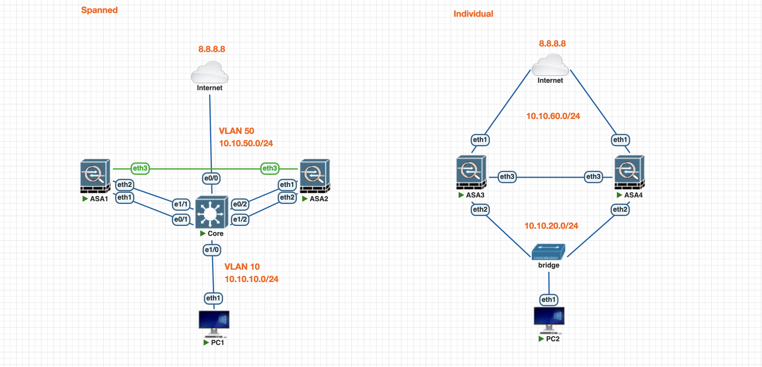
A Cisco ASA (Adaptive Security Appliance) cluster enables multiple ASAs to work together for high availability and load balancing, enhancing network security and performance. In clustering, traffic is distributed across multiple ASAs for redundancy and fault tolerance.
Spanned Mode:
- All cluster members share a common MAC address for outside interfaces.
- Incoming traffic is distributed across all ASAs in the cluster.
- Suitable for load balancing across multiple devices.
Individual Mode:
- Each ASA in the cluster has its own unique MAC address.
- Traffic is not shared; each ASA handles its own connections.
- Suitable for scenarios where failover rather than load balancing is prioritized.
Spanned Mode
First we configure the VLAN and Port-Channel on the Core Switch side
1
2
3
4
5
6
7
8
9
10
11
12
13
14
15
16
17
18
19
20
21
22
23
24
25
26
27
28
29
30
31
32
vlan 50
name outside
vlan 10
name inside

int e0/0
 switchport mode access
 switchport access vlan 50

int range e0/1-2
 switchport mode access
 switchport access vlan 50
 channel-group 1 mode active

int port-channel 1
 switchport mode access
 switchport access vlan 50
 no shut

int e1/0
 switchport mode access
 switchport access vlan 10

int range e1/1-2
 switchport mode access
 switchport access vlan 10
 channel-group 2 mode active

int port-channel 2
 switchport mode access
 switchport access vlan 10
 no shut

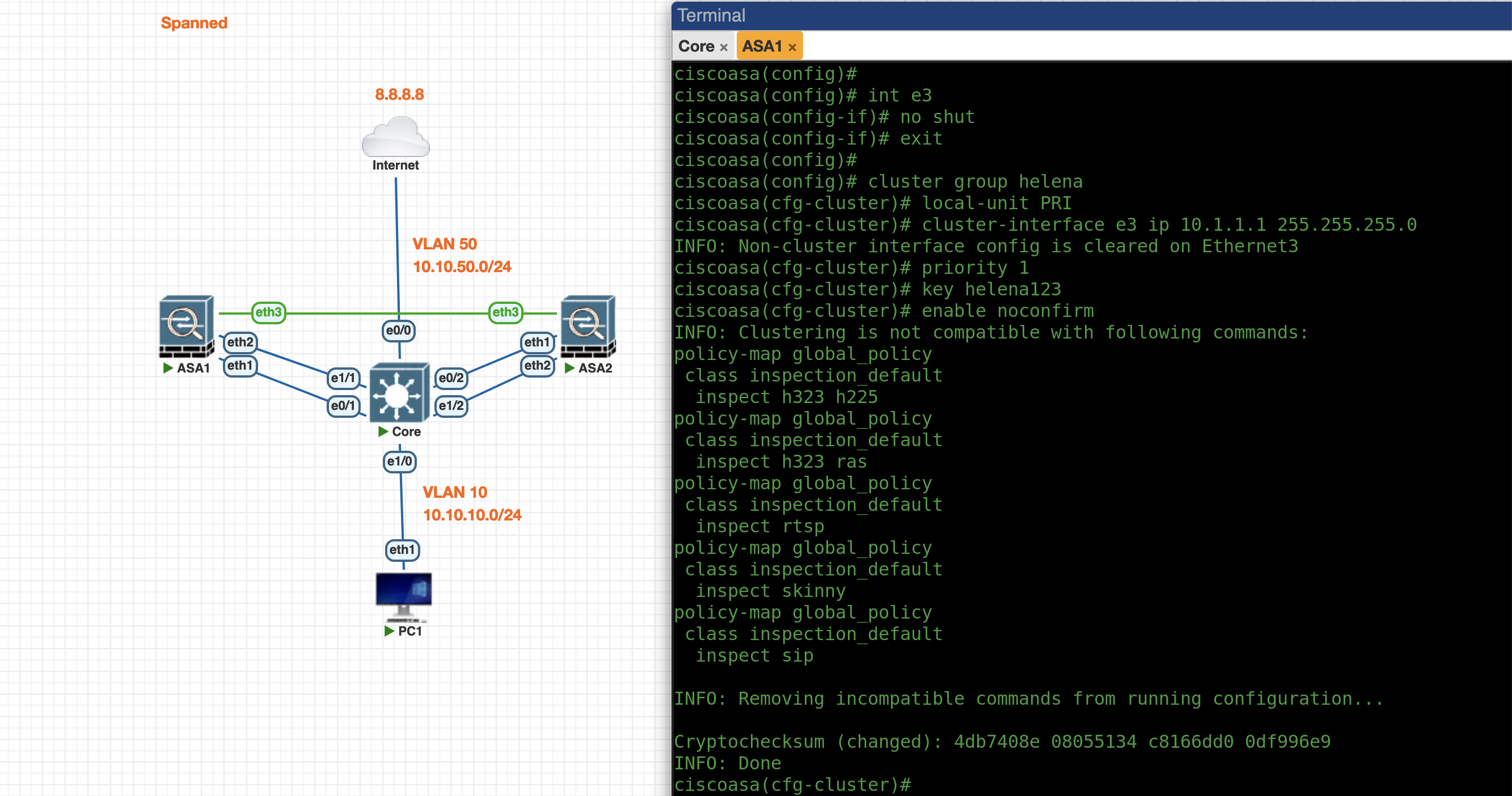
Next we configure the Spanned Cluster on the ASA1 side
1
2
3
4
5
6
7
8
9
10
11
int e3
no sh

cluster interface-mode spanned

cluster group helena
local-unit PRI
cluster-interface e3 ip 10.1.1.1 255.255.255.0
priority 1
key helena123
enable noconfirm
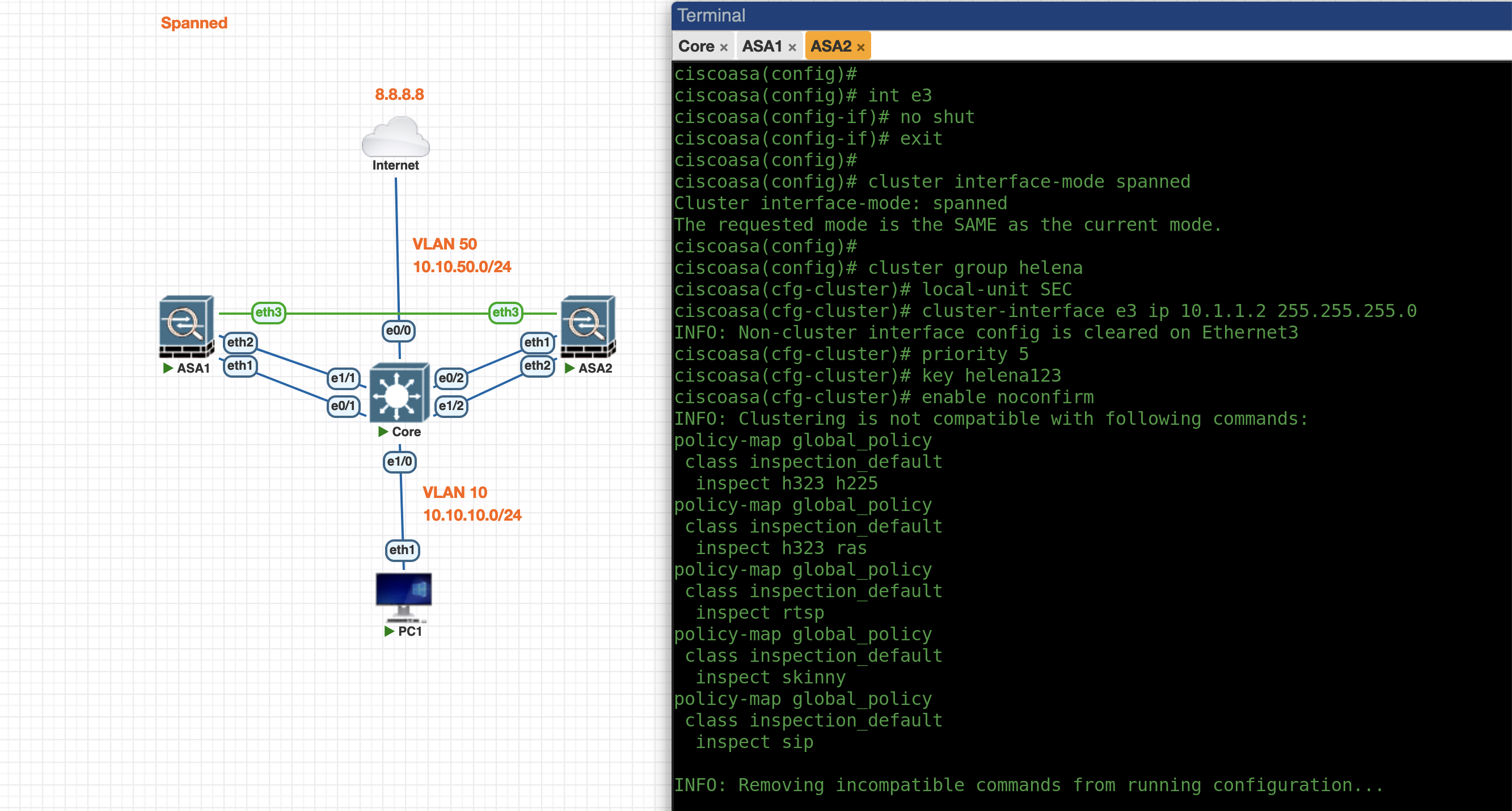
Next do the same on the ASA2 side
1
2
3
4
5
6
7
8
9
10
11
12
int e3
no sh

cluster interface-mode spanned

cluster group helena
local-unit SEC
cluster-interface e3 ip 10.1.1.2 255.255.255.0
priority 10
key helena123
enable noconfirm
At this point we have configure the Cluster and now its up and running
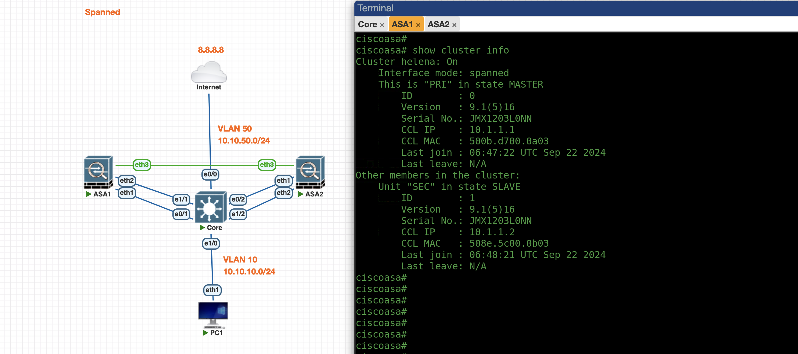
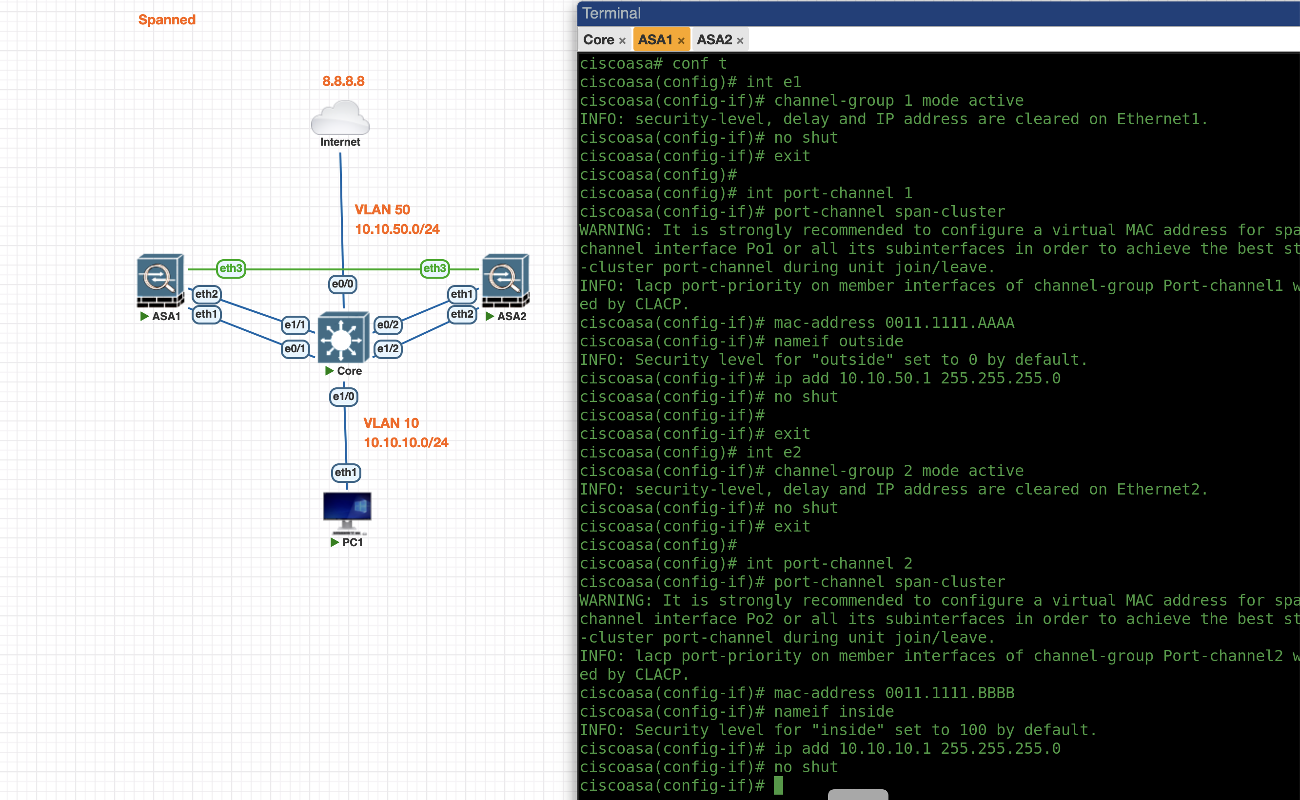
Now that the cluster is up, all configuration is done on the Master side. We’ll configure the Port Channel on the Outside and Inside interface
1
2
3
4
5
6
7
8
9
10
11
12
13
14
15
16
17
18
19
20
21
22
23
int e1
channel-group 1 mode active
no shut
exit

int po1
port-channel span-cluster
mac-address 0001.111.AAAA
nameif outside
ip add 10.0.137.11 255.255.255.0
no shut

int e2
channel-group 2 mode active
no shut
exit

int po2
port-channel span-cluster
mac-address 0001.111.BBBB
nameif inside
ip add 10.0.100.11 255.255.255.0
no shut
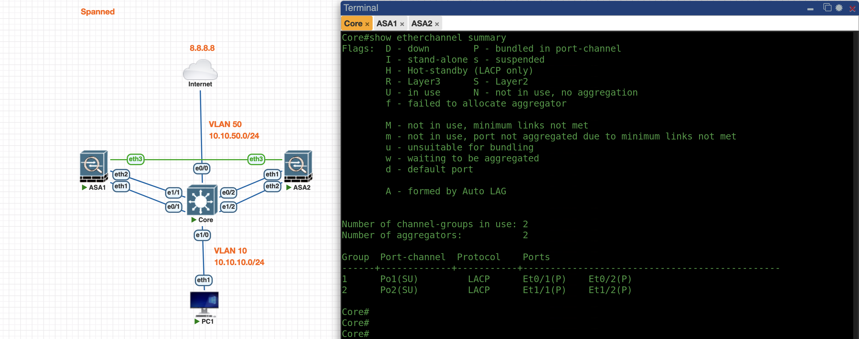
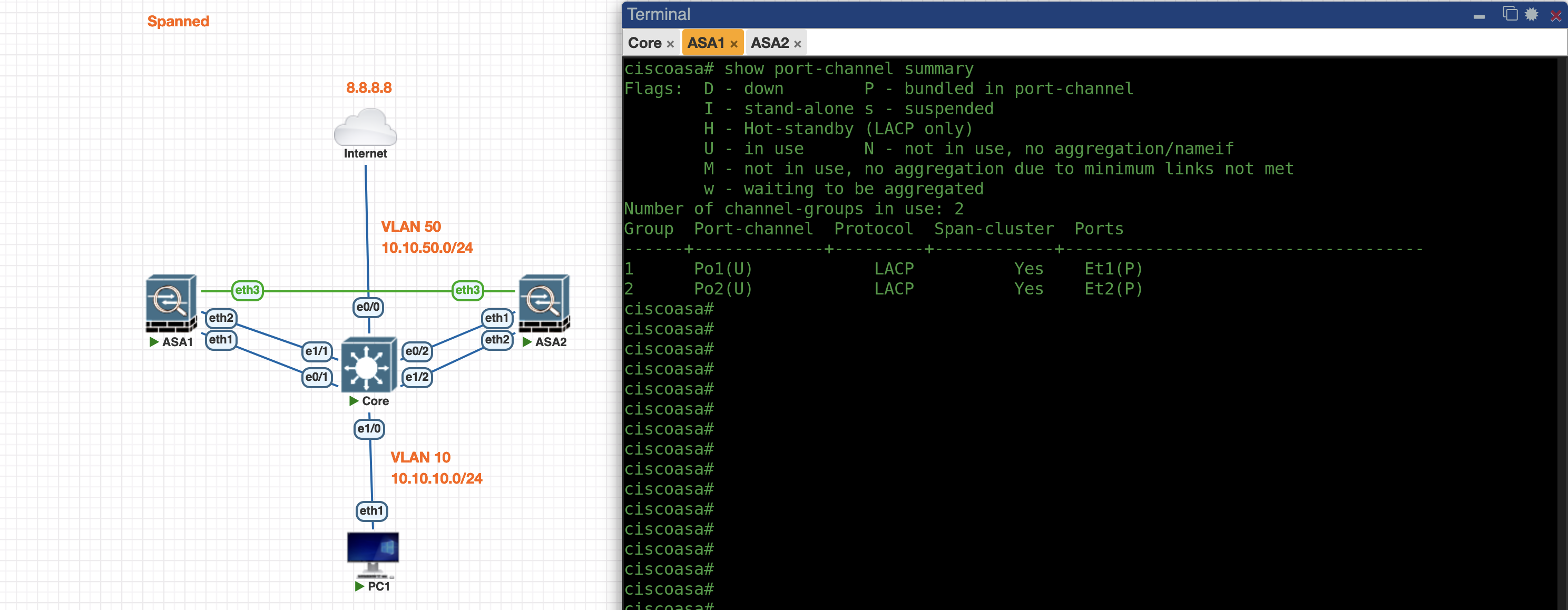
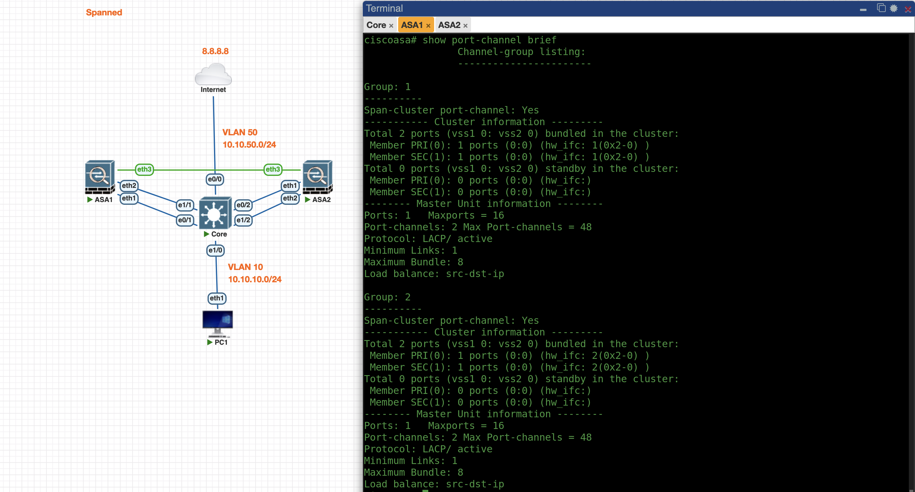
Now the Port-Channel between Core and ASA is up
Core
ASA
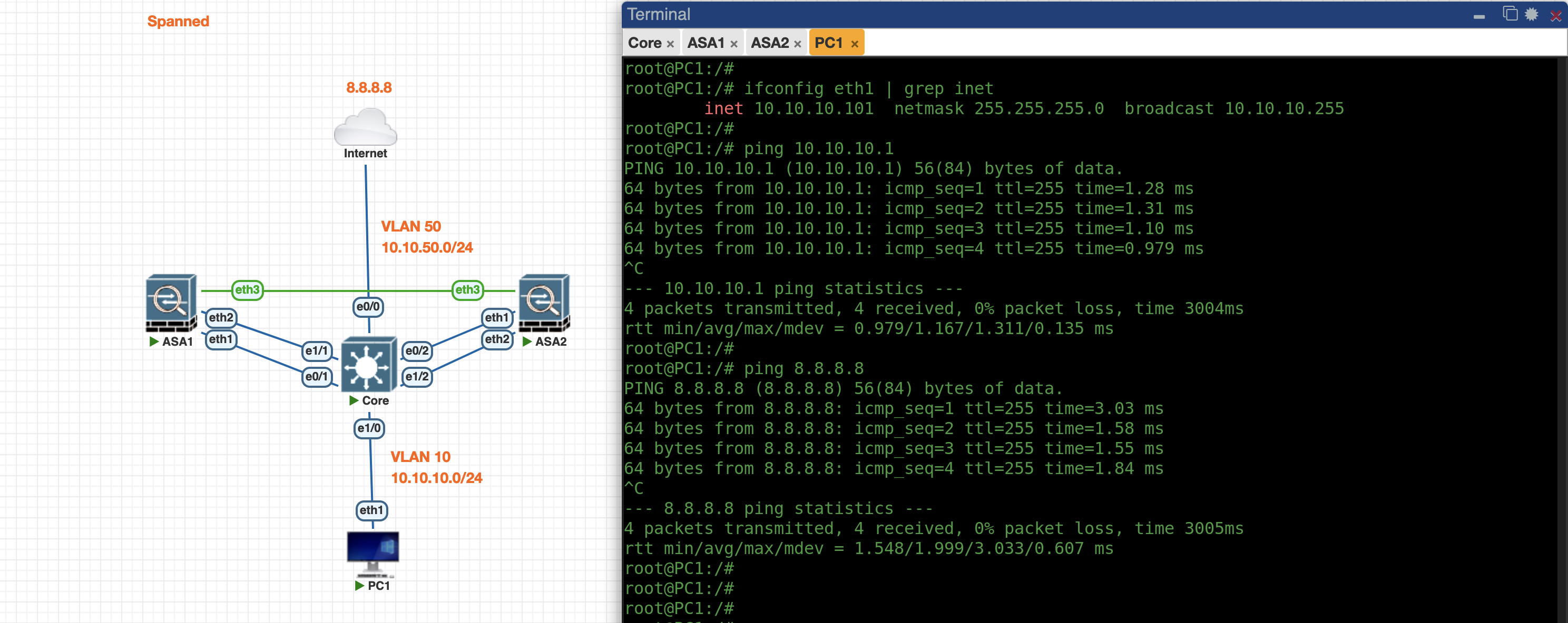
On the PC side, we can now ping the ASA as well as to access the internet
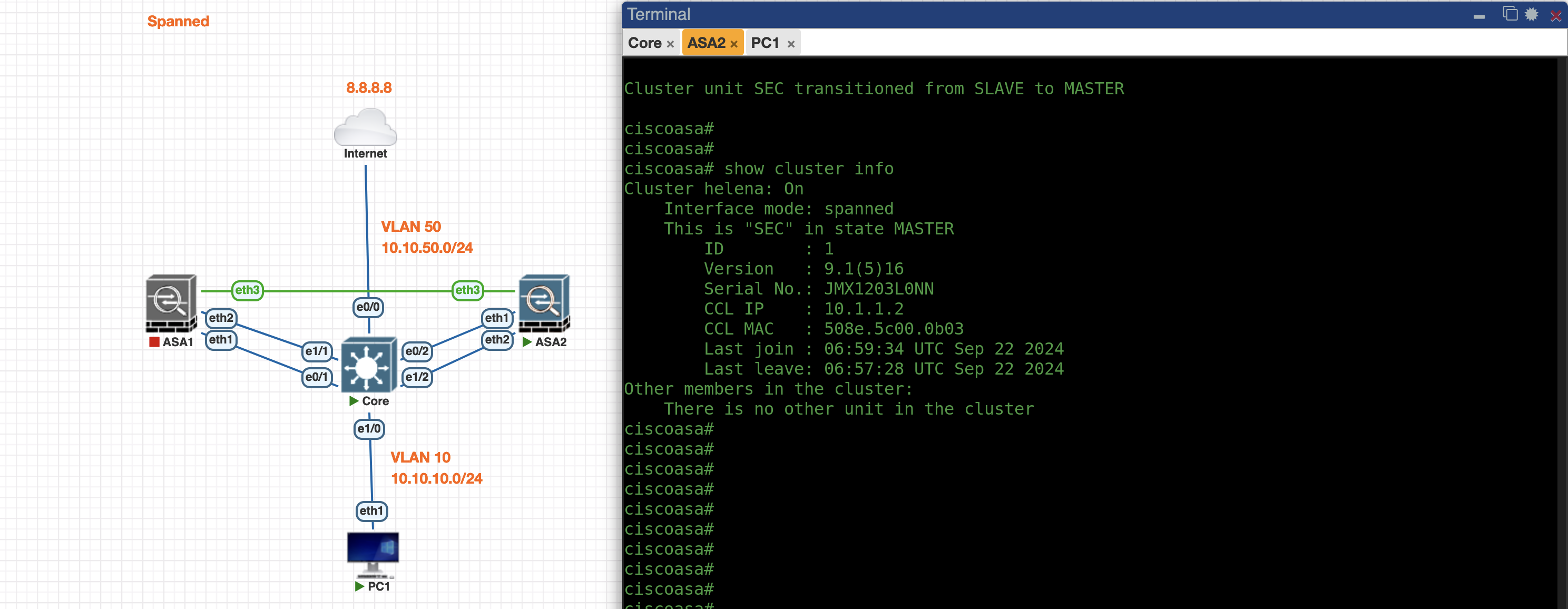
If we shut down the Primary ASA, the Secondary ASA will take over the primary role while maintaining the traffic connectivity passing through the port-channel
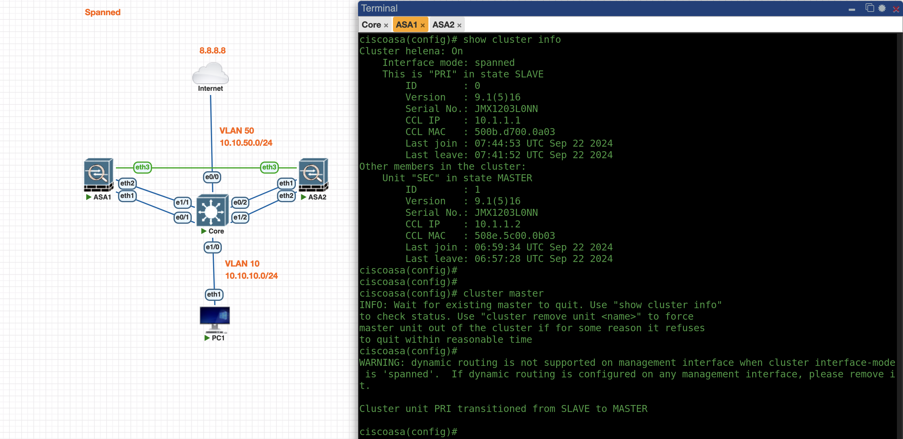
When turning on the ASA1 again, it’ll stay on the Slave role until command “cluster master” initiated
Individual Mode
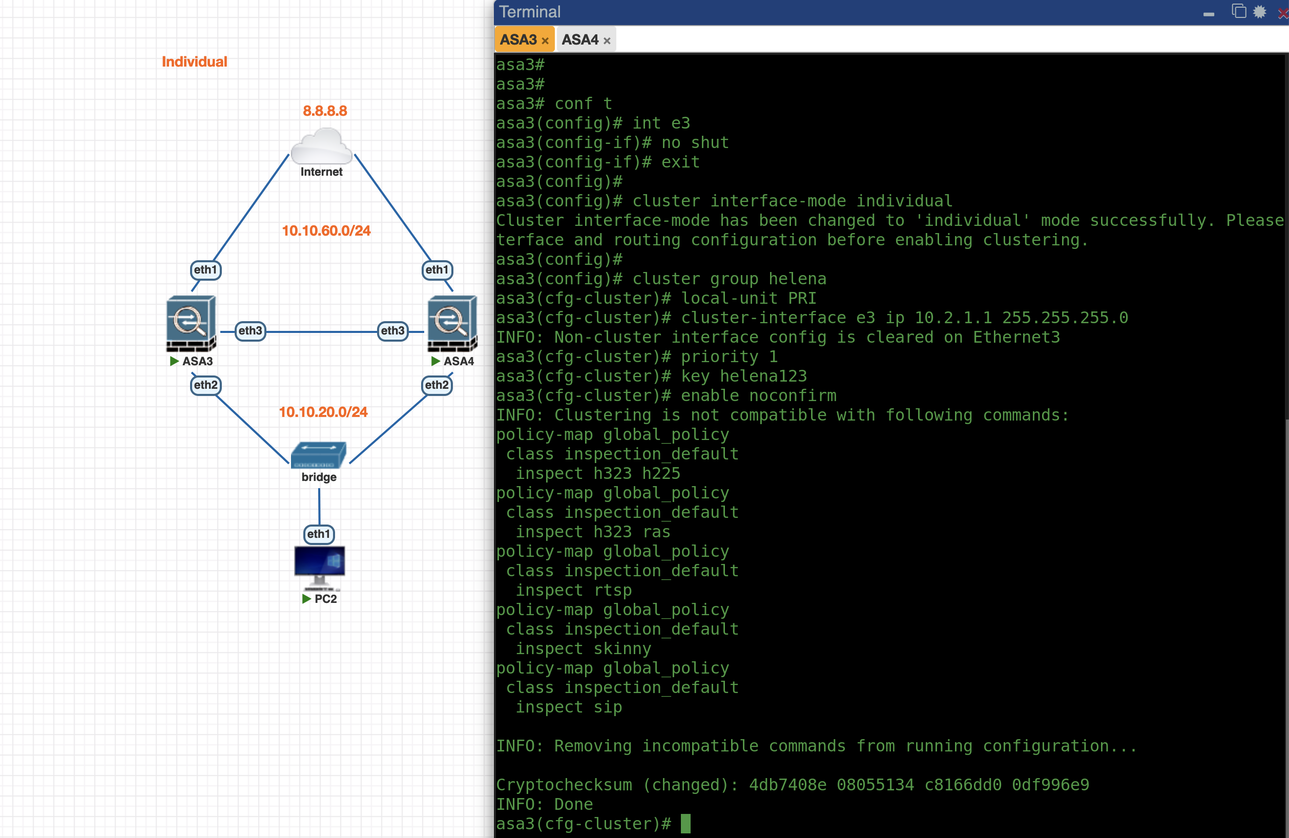
First lets enable Individual Mode Cluster on ASA3, the config is pretty much the same as previously
1
2
3
4
5
6
7
8
9
10
11
int e3
no sh

cluster interface-mode individual

cluster group helena
local-unit PRI
cluster-interface e3 ip 10.2.1.1 255.255.255.0
priority 1
key helena123
enable noconfirm
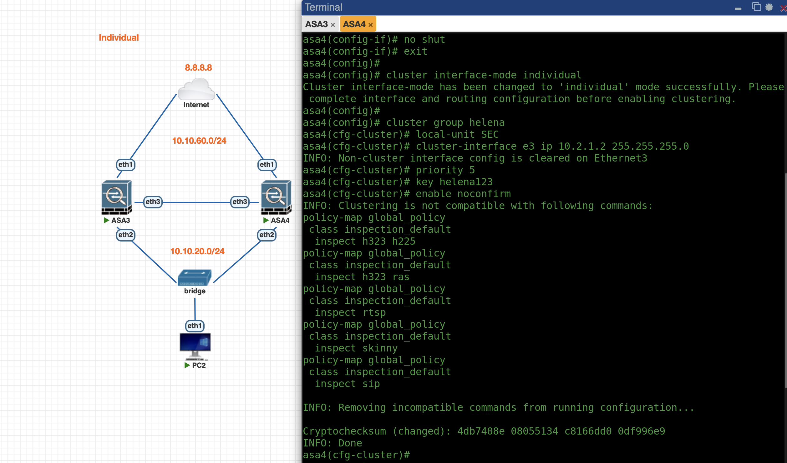
Do the same on ASA4
1
2
3
4
5
6
7
8
9
10
11
12
int e3
no sh

cluster interface-mode individual

cluster group helenag
local-unit SEC
cluster-interface e3 ip 10.2.1.2 255.255.255.0
priority 10
key helena123
enable noconfirm
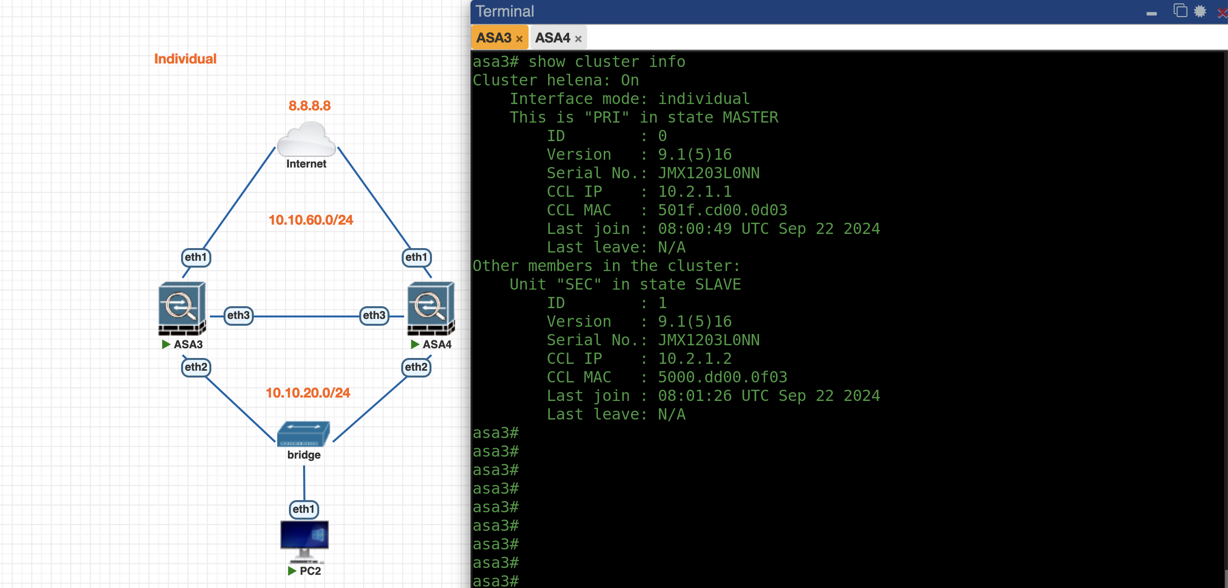
And with that, the Cluster is up
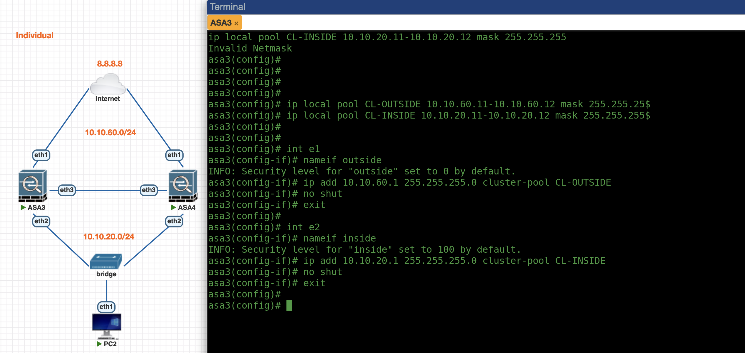
Next we configure the IP Pool for each ASA node on Outside and Inside interface and assign them to the interfaces
1
2
3
4
5
6
7
8
9
10
11
12
13
14
15
ip local pool CL-OUTSIDE 10.10.60.11-10.10.60.12 mask 255.255.255.0
ip local pool CL-INSIDE 10.10.20.11-10.10.20.12 mask 255.255.255.0

interface e1
 nameif outside
 security-level 0
 ip address 10.10.60.1 255.255.255.0 cluster-pool CL-OUTSIDE
 no shut

interface e1
 nameif inside
 security-level 100
 ip address 10.10.20.1 255.255.255.0 cluster-pool CL-INSIDE
 no shut
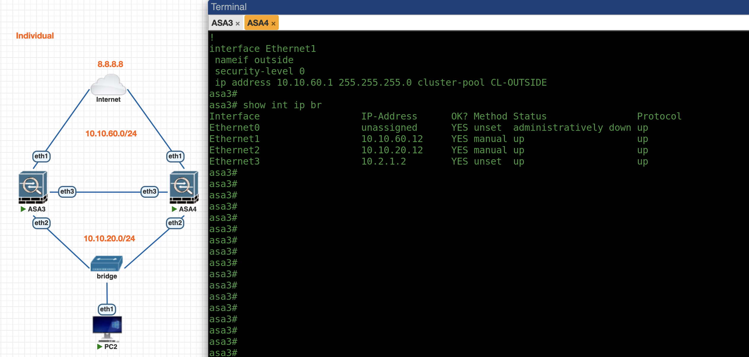
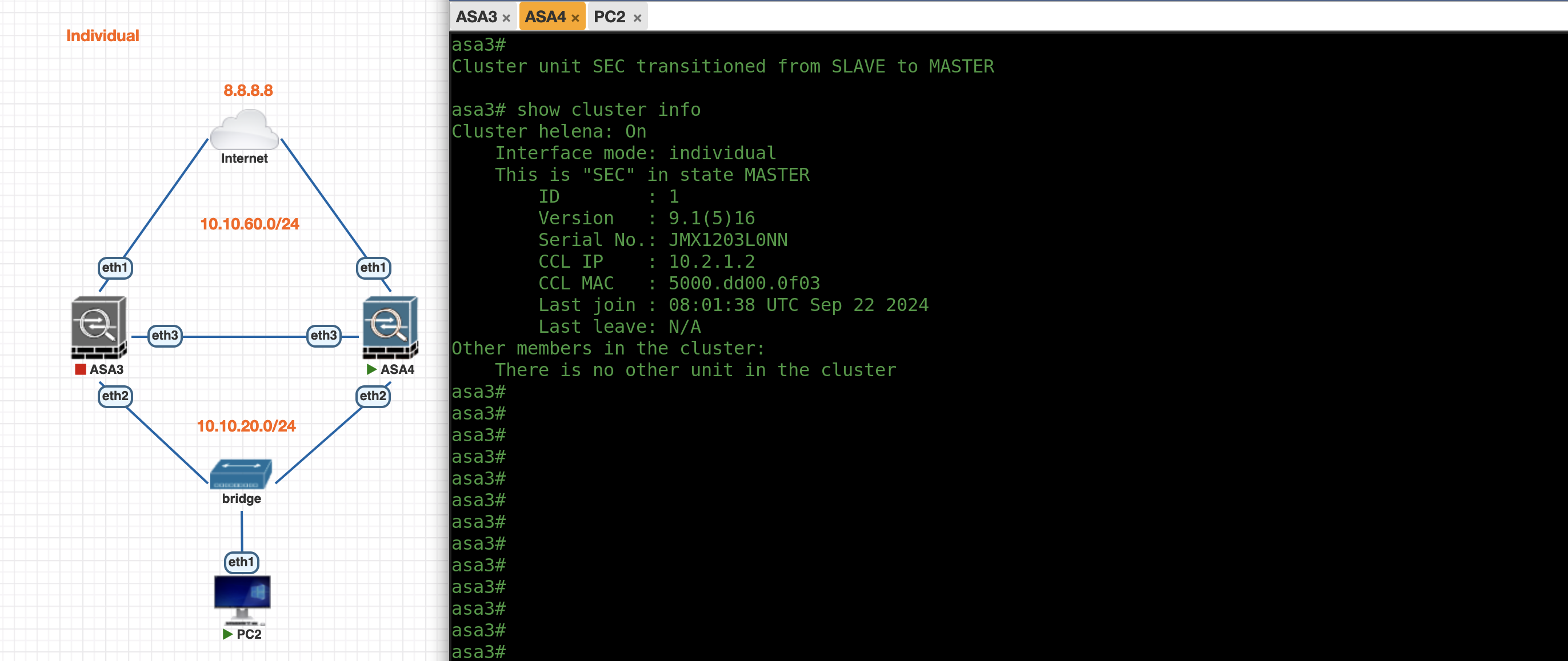
Now we can see both ASAs have obtained each of their IP Addresses from the pool
ASA3
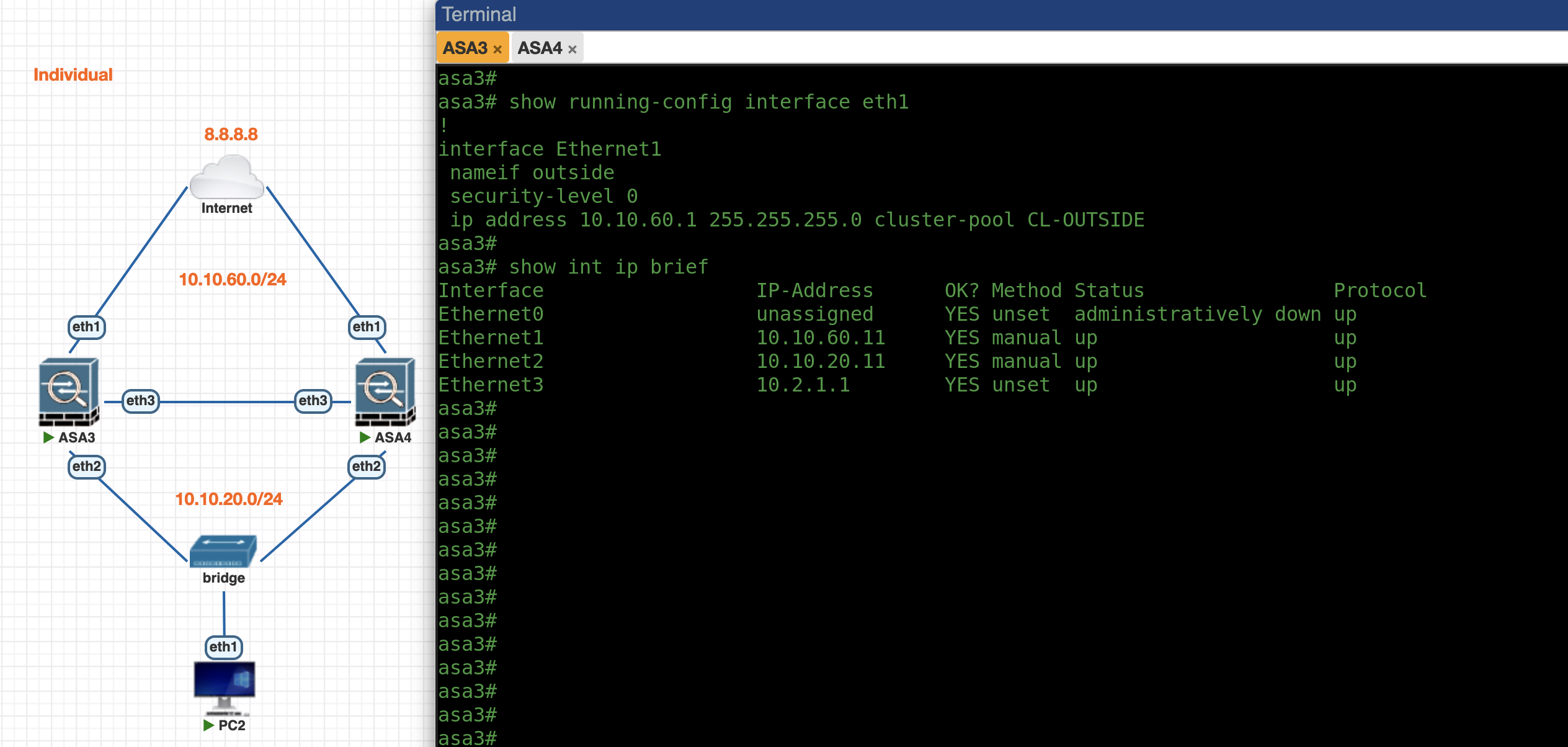
ASA4
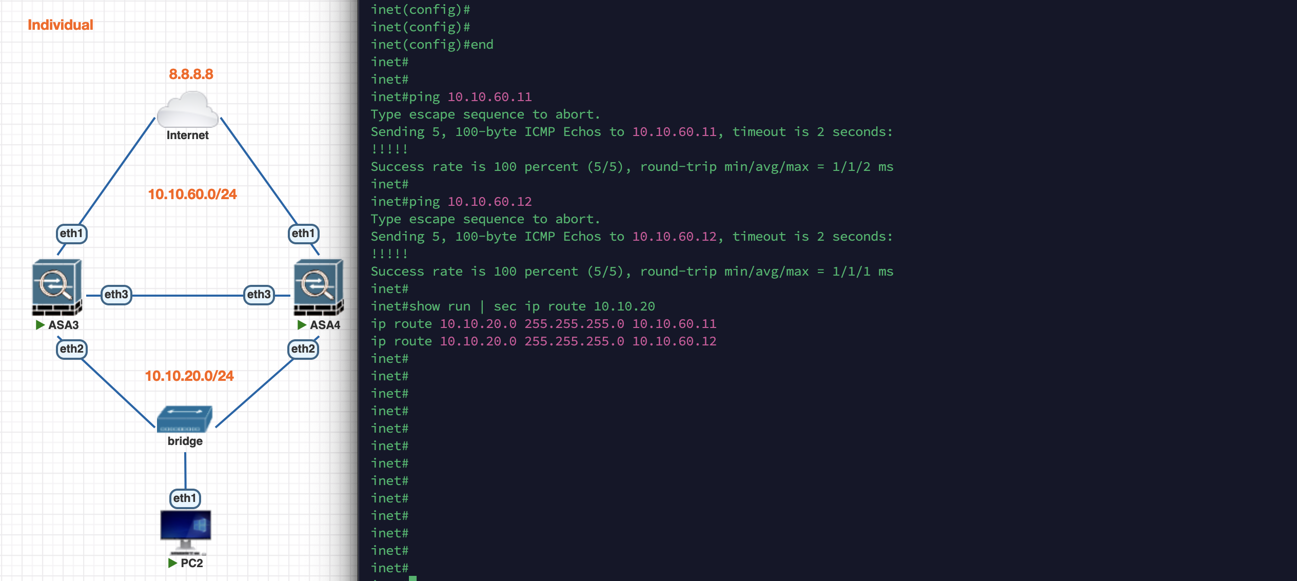
On the Inet Router side, we can now ping .1, .11, and also .12. Here we’ll make 2 static routes to both ASA addresses to enable ECMP load balancing. Here we can also add IP SLA Tracking to automatically remove the route if the gateway is unreachable but we’ll keep it simple for the sake of this demo
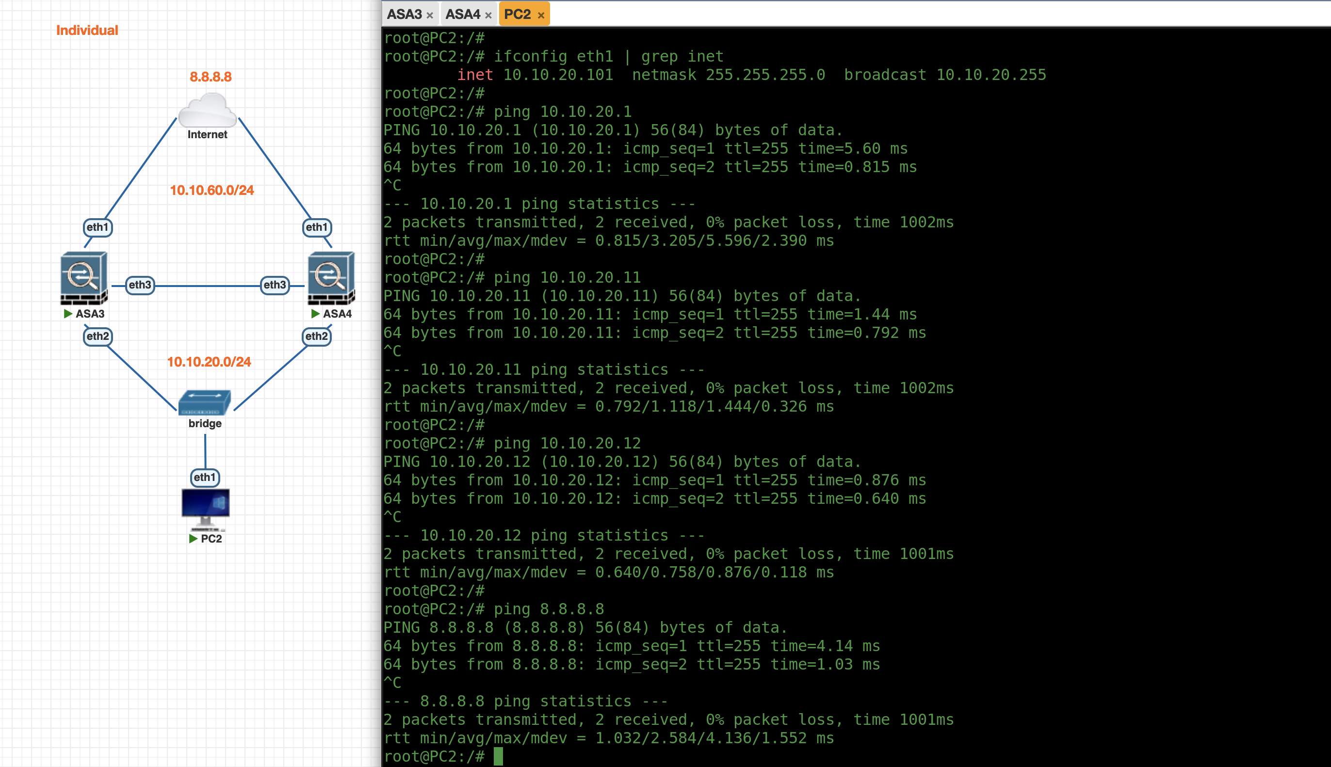
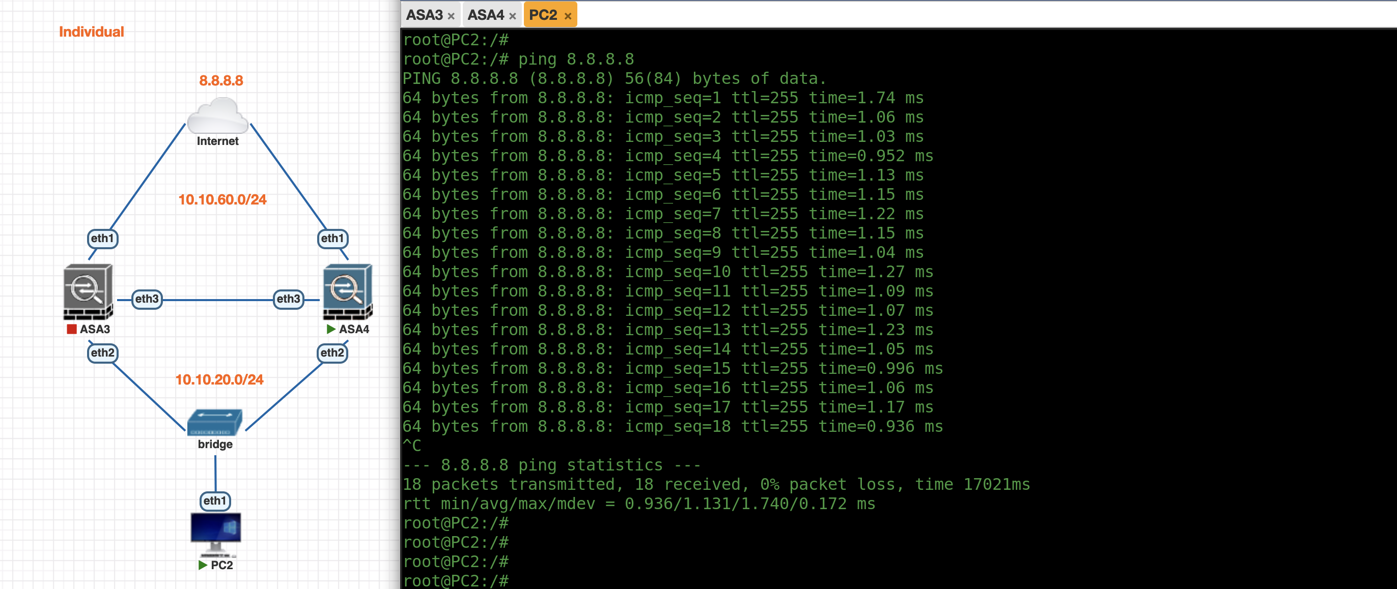
On the PC side, we can ping all the ASA’s IP Addresses and also able to access the internet
If we shut down ASA3, ASA4 will take over the Master Role
And traffic from PC will still be handled by the remaining active node, assuming its gateway is pointing to the ASA4
High Availability
Cisco ASA High Availability (HA) Active-Standby allows two ASAs to operate as a pair for redundancy. In this setup, one ASA is active and processes traffic, while the standby unit remains idle, ready to take over if the active unit fails, ensuring continuous network availability.
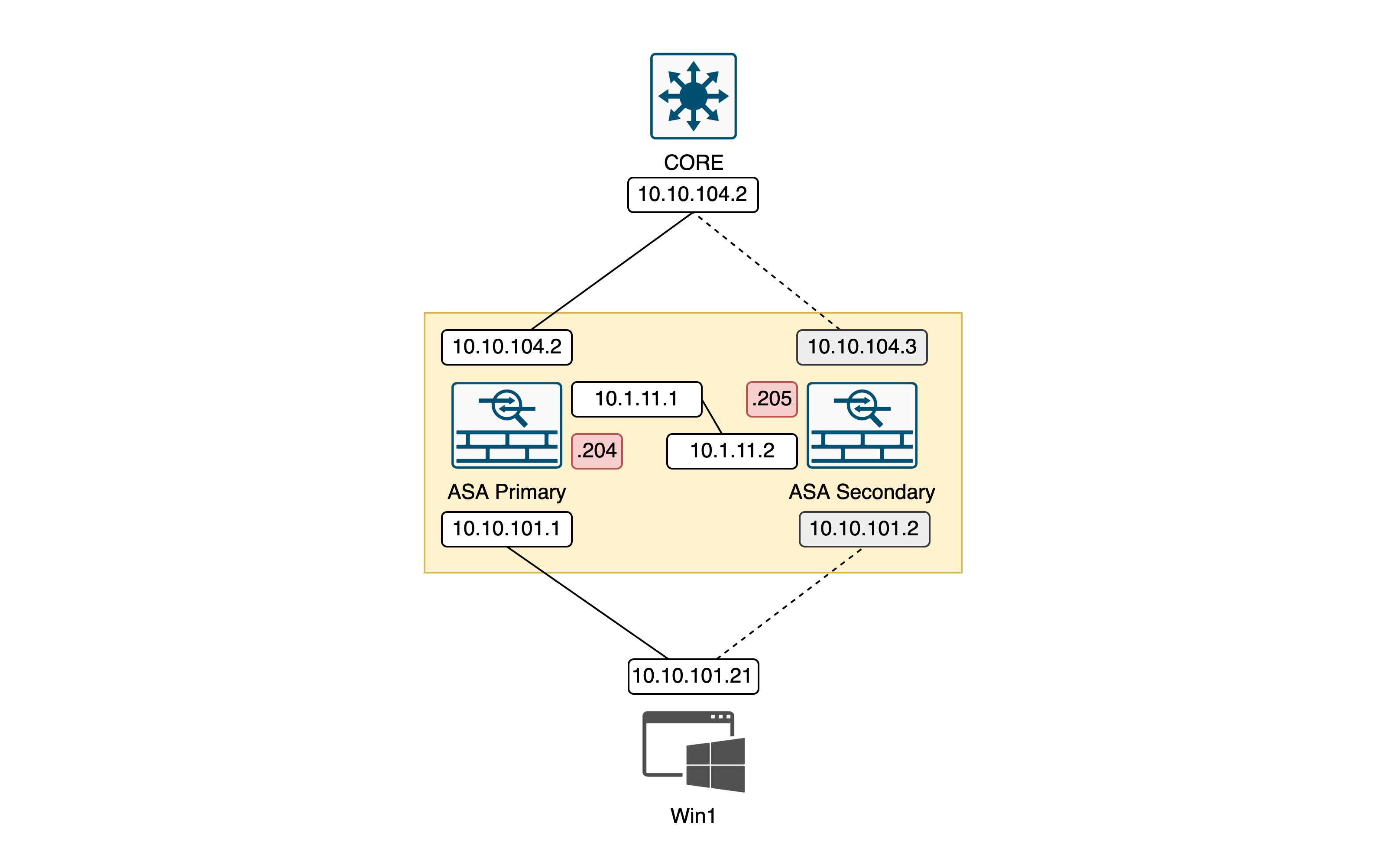
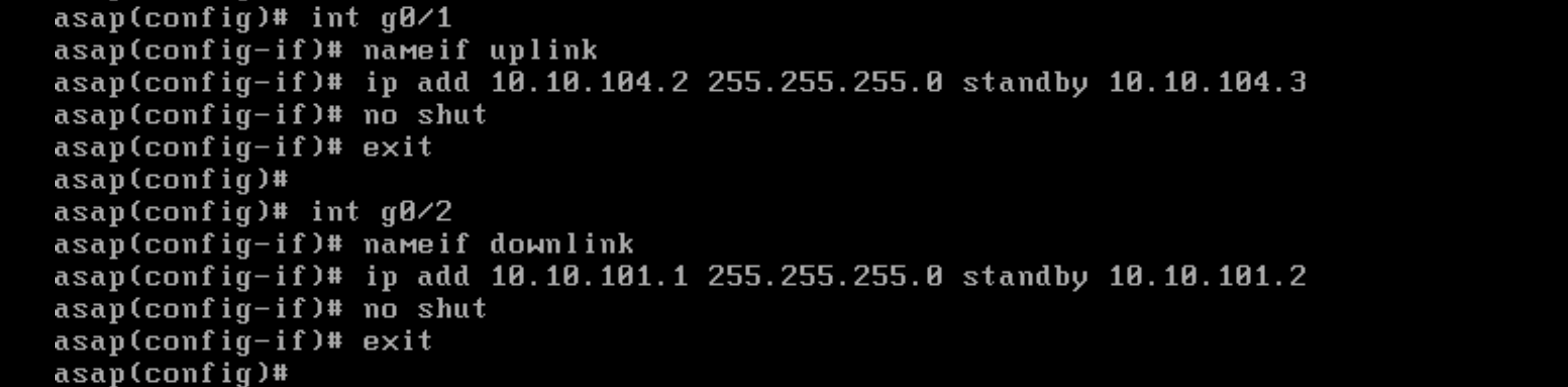
Firstly on the Primary Node, we’re configuring the IP Address followed by its standby IP Address
1
2
3
4
5
6
7
8
9
10
11
int g0/1
nameif uplink
ip add 10.10.104.2 255.255.255.0 standby 10.10.104.3
security-level 100
no shut

int g0/2
namif downlink
ip add 10.10.101.1 255.255.255.0 standby 10.10.101.2 255.255.255.0
security-level 0
no shut
Next we add failover configuration, this command will use G0/3 interface as the HA link
1
2
3
4
5
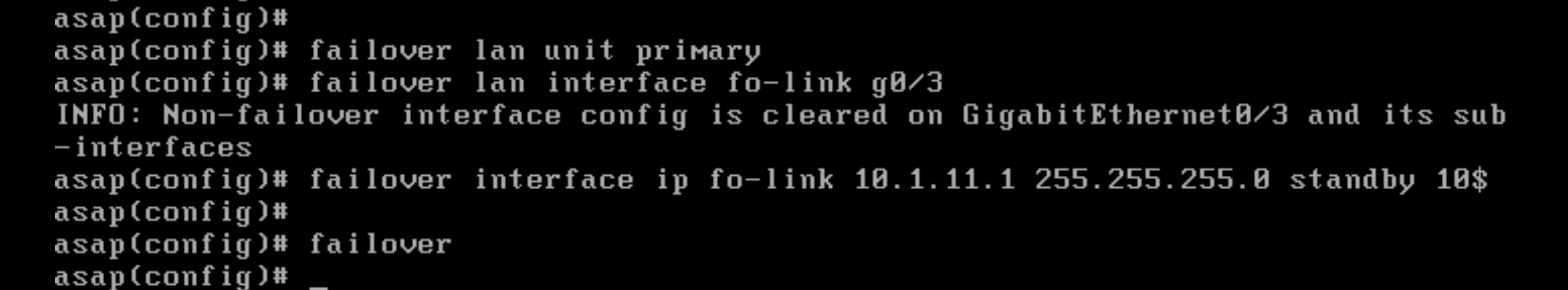
failover lan unit primary
failover lan interface fo-link g0/3
failover interface ip fo-link 10.1.11.1 255.255.255.0 standby 10.1.11.2
failover
Then unshut the G0/3 interface for the failover configuration to activate

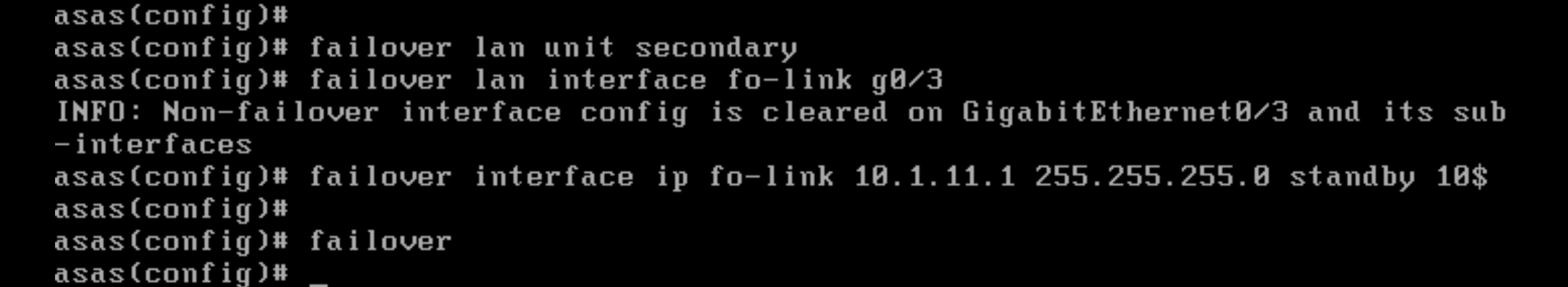
On the Secondary Node, we just need to add the failover configuration, because other configs will be synced from the Primary later
1
2
3
4
5
failover lan unit secondary
failover lan interface fo-link g0/3
failover interface ip fo-link 10.1.11.1 255.255.255.0 standby 10.1.11.2

failover
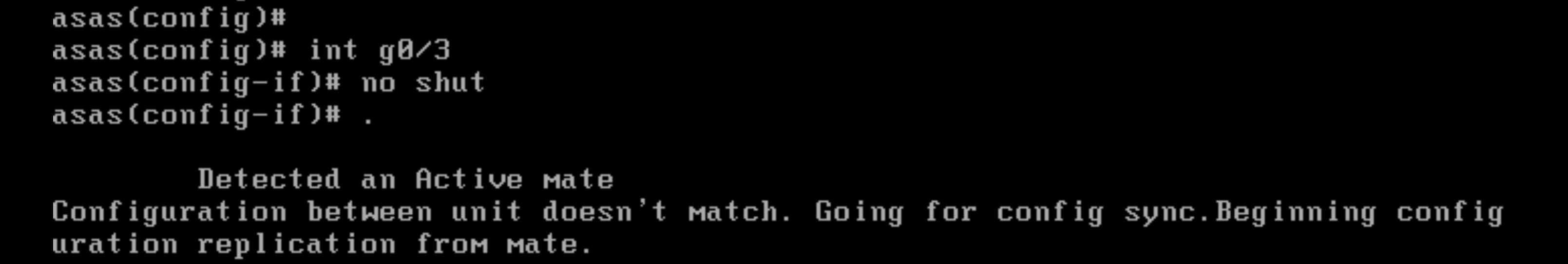
Unshut the G0/3 interface and the failover sequence will start
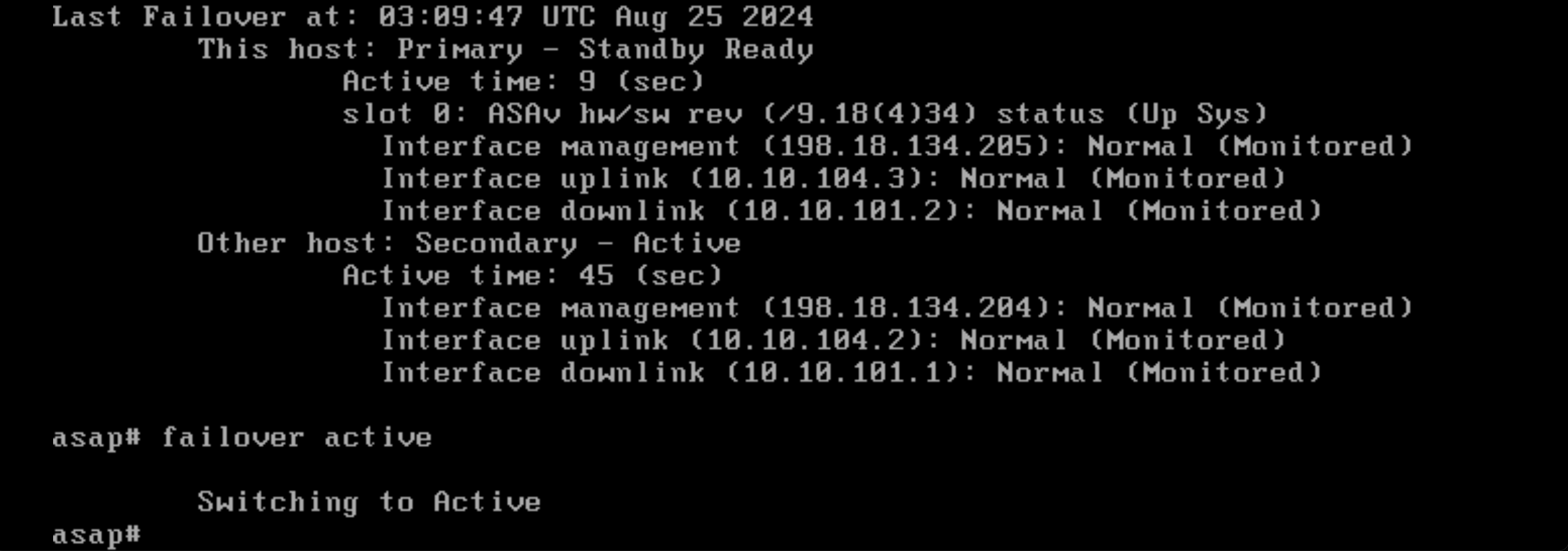
Running “show failover” on Primary shows that it is the active node
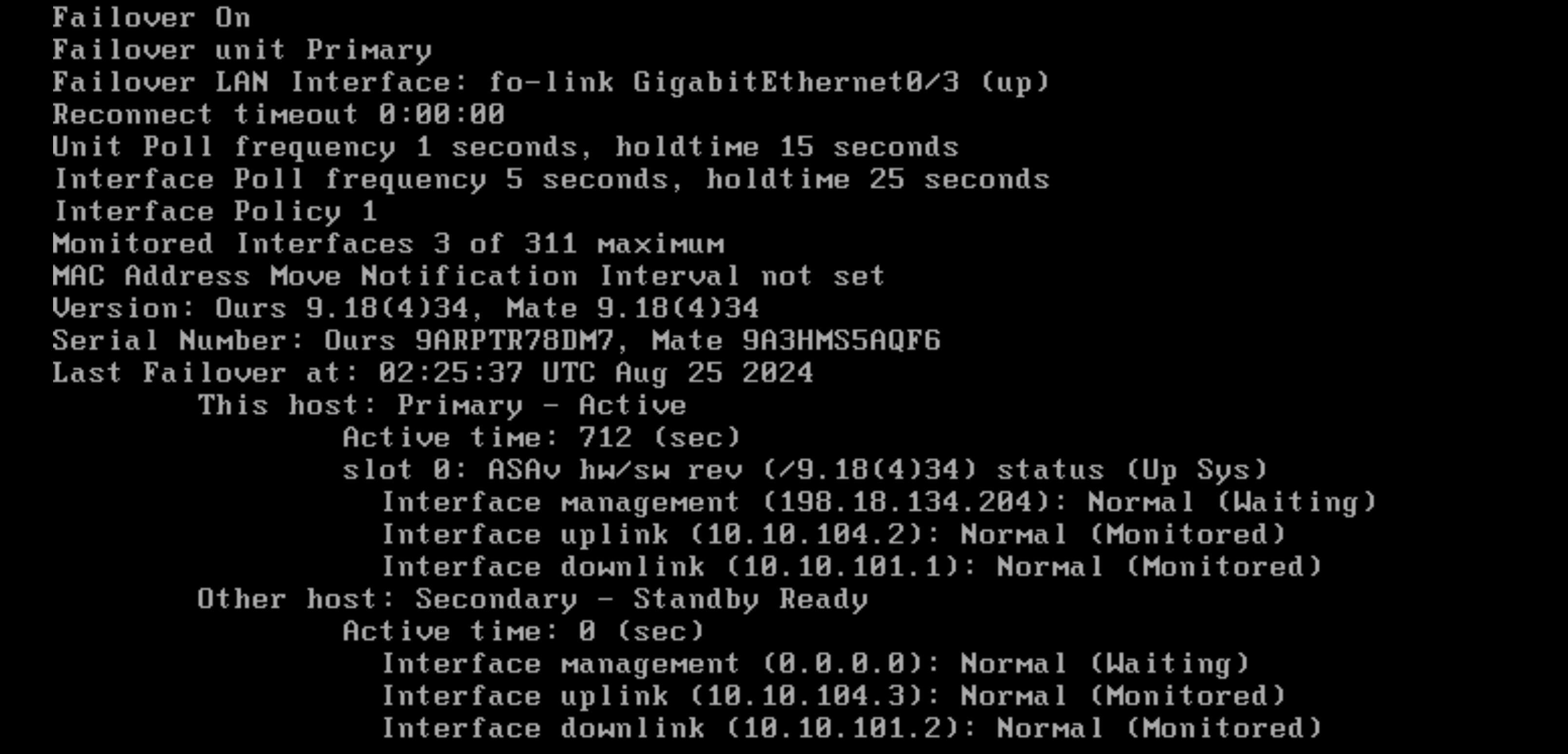
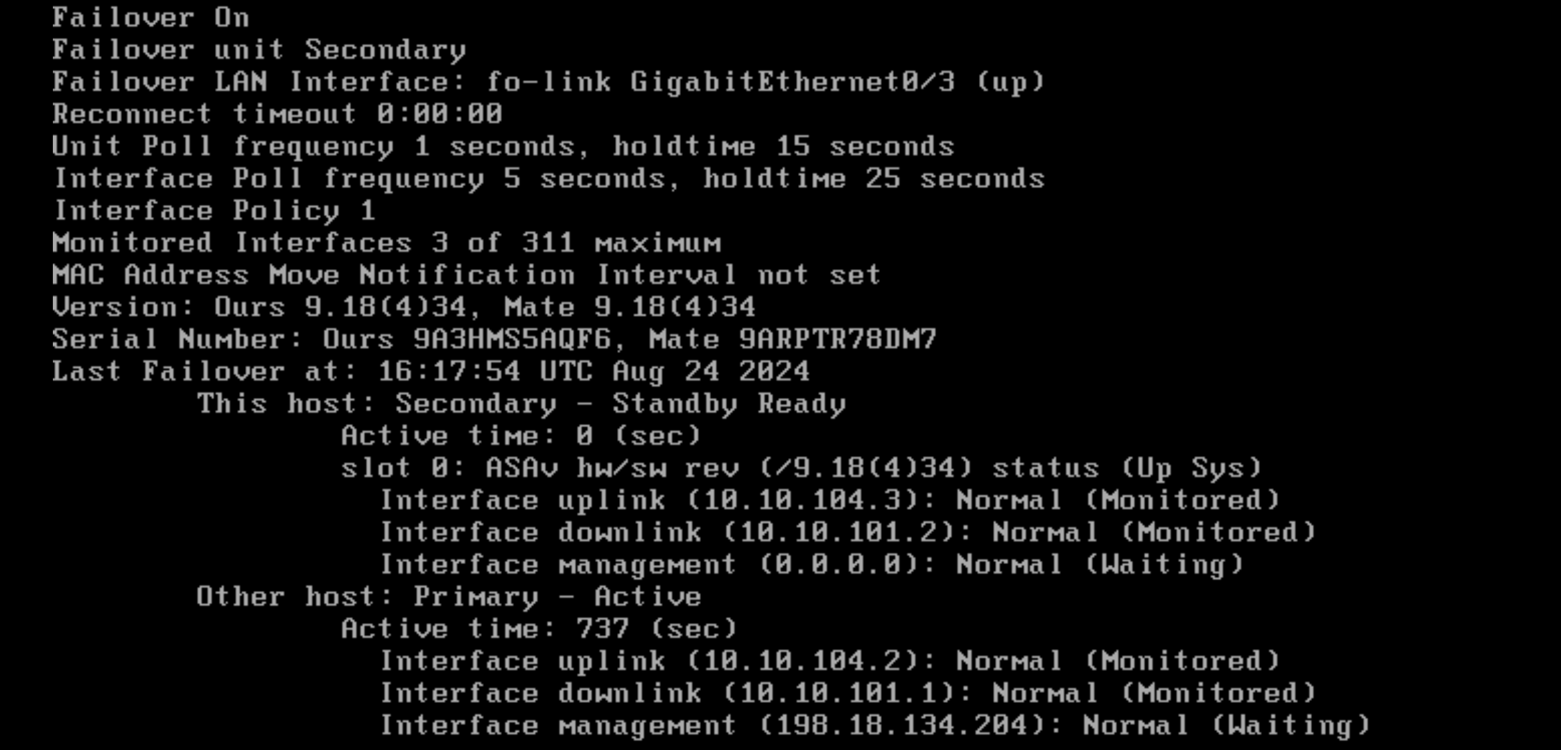
On the Secondary it detects itself as the standby node
Failing Over
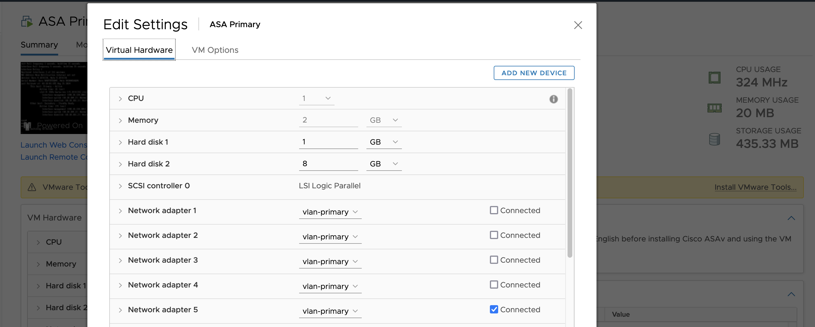
Lets simulate a network failure by disconnecting some interfaces on the Primary Node
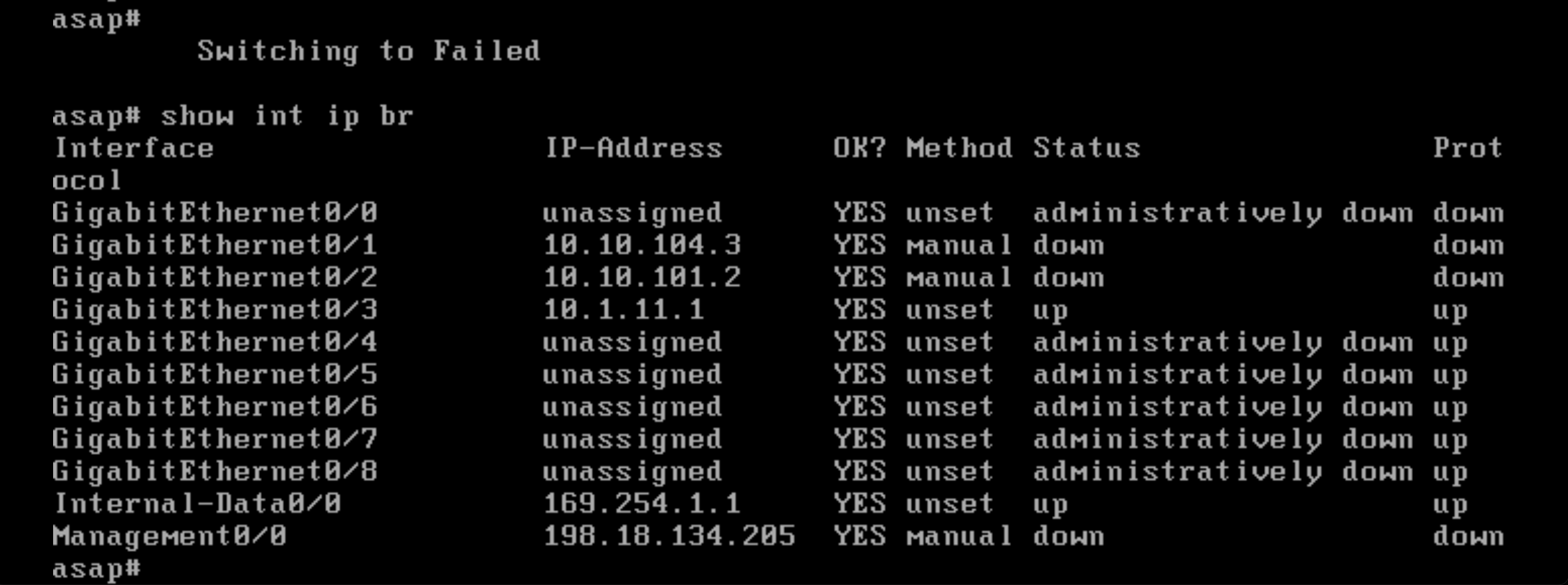
The Primary will immediately switch itself into Failed state and take the standby configuration
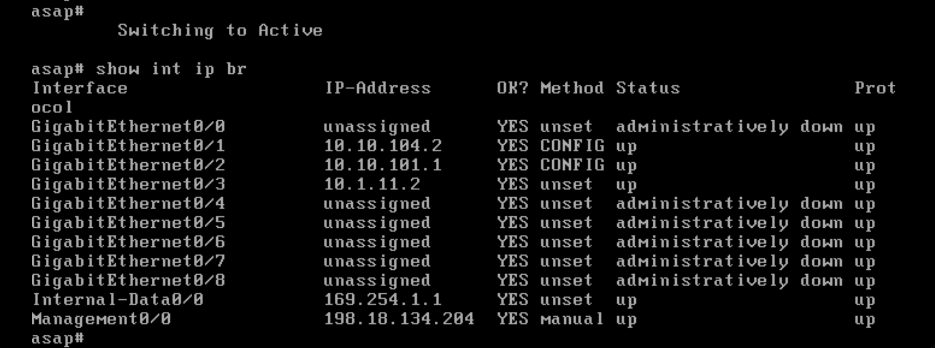
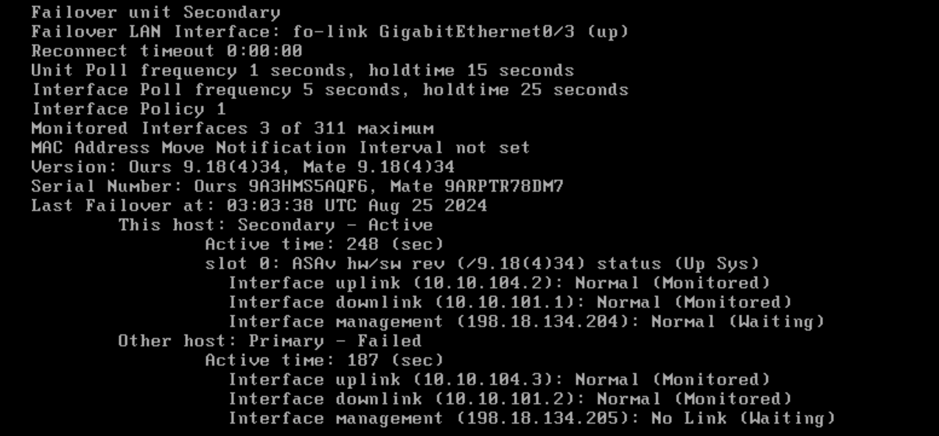
The Secondary will take the active role and take the active configuration
Running “show failover” shows that the secondary is indeed the active node
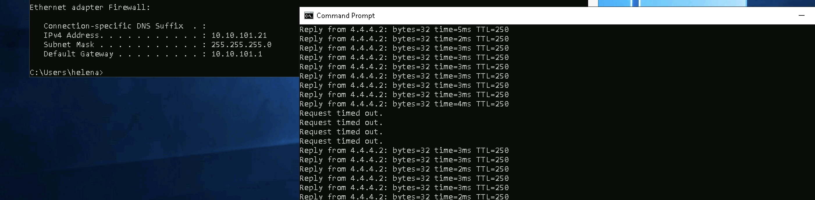
There’s some outage but nothingg significant on the client side when the failover happens
Switching Back
Now lets restore the network functionality on the Primary Node, it will make the node change its state from Failed to Standby.
To actually claim the active role again, run “failover active”