Fortinet Hub-and-Spoke SD-WAN with ADVPN
Hub-and-Spoke SD-WAN with ADVPN is a setup where a central hub connects to multiple remote branch offices using SD-WAN technology. The use of ADVPN means that the VPN connections between the hub and spokes are established automatically and dynamically, simplifying network management and ensuring efficient and secure communication between all network locations.
- Hub-and-Spoke: In this topology, there is a central hub that connects to multiple remote branch offices (spokes). The hub serves as a central point for network management and traffic distribution
- ADVPN (Auto Discovery VPN): ADVPN is a feature in VPN that allows dynamic and automatic establishment of VPN connections between different network endpoints. Instead of configuring VPN tunnels manually for each remote site, ADVPN automatically discovers and establishes VPN connections as needed.
Network Topology
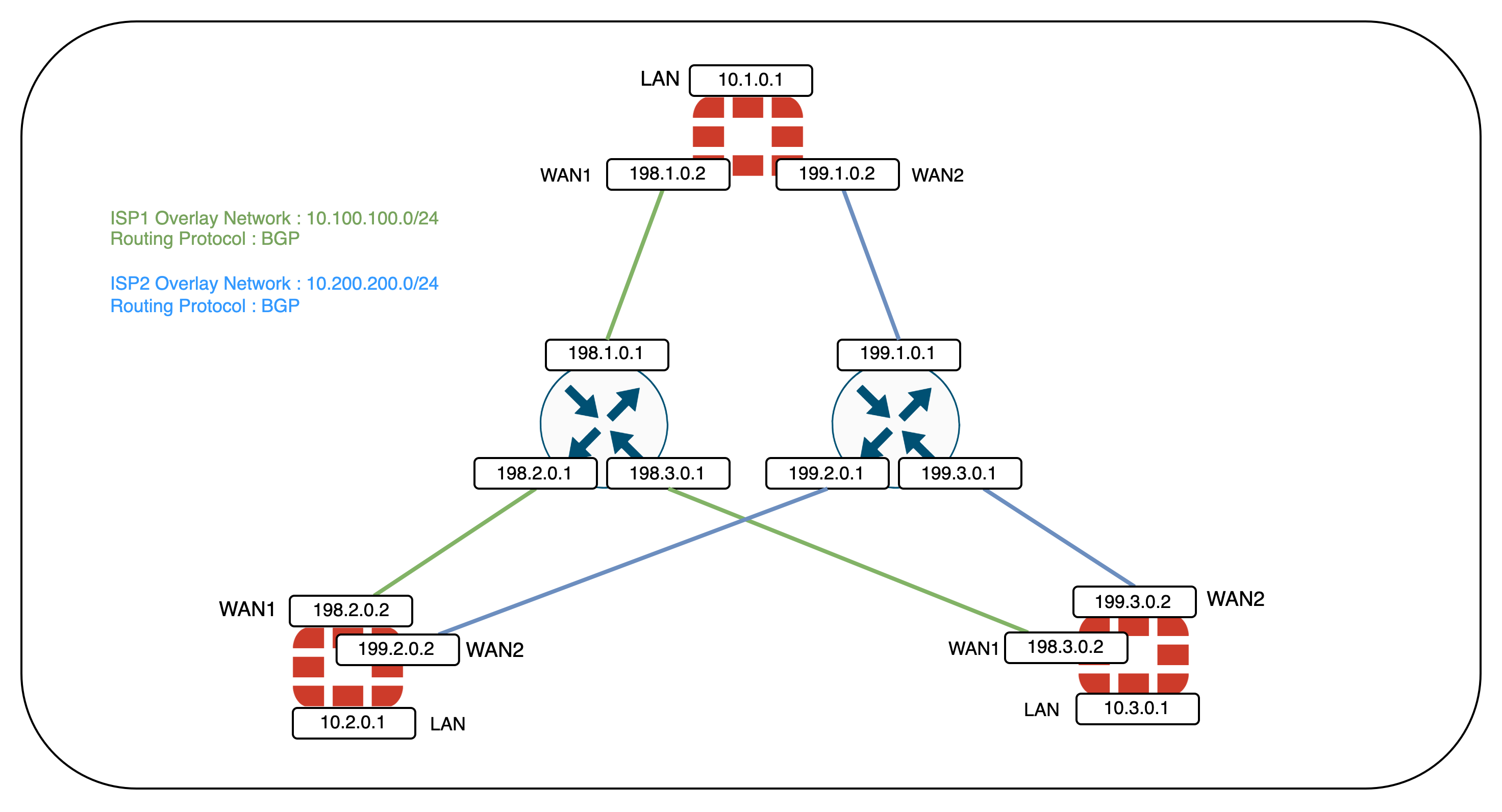
Here’s the network topology for this deployment, where we also have BGP as the overlay network to handle the routing of traffic between different SD-WAN edges
Configuring the Hub on Site 1
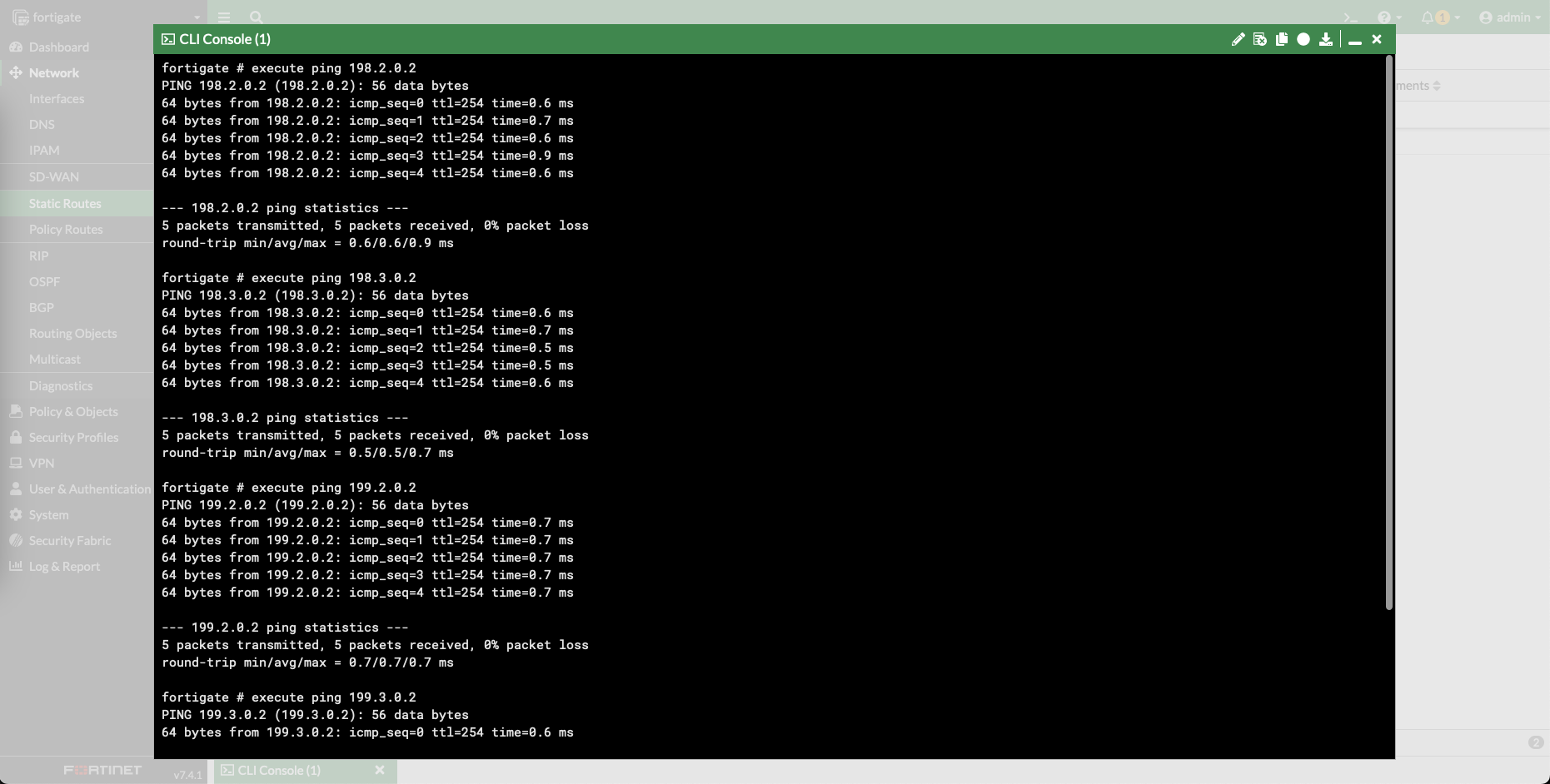
First of all, make sure all devices within the deployment are able to reach each other
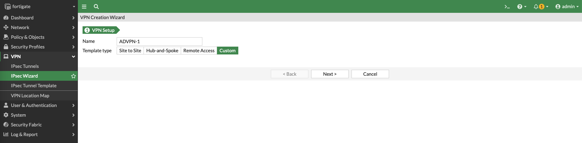
Next configure the IPSec VPN for WAN 1
Configure the Remote Gateway to be Dialup User, disable Add Route, and enable Auto Discovery Sender
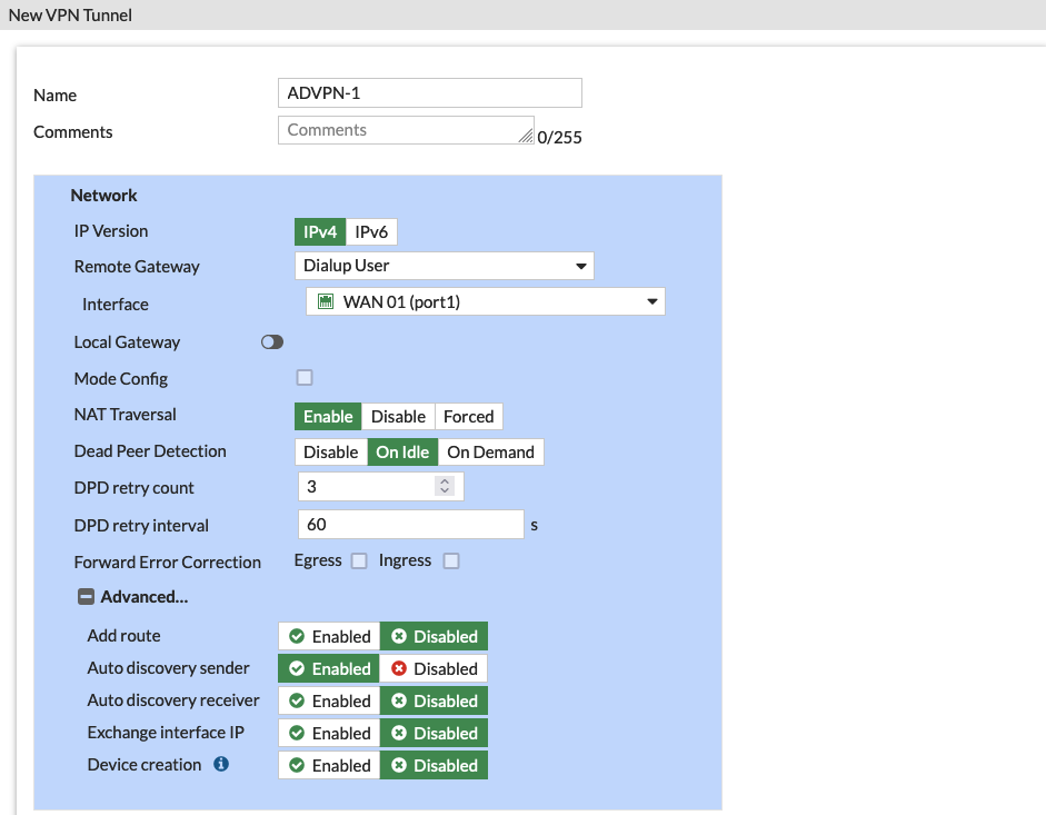
- Dialup User allows Spokes to dynamically form a Tunnel Connection to Hub, thus allowing multiple Spokes to establish IPSec VPN to Hub
- Disable Add Route ensures IKE doesn’t add routes when dynamic tunnel is negotiated, because routing will be handled by BGP
- Auto Discovery Sender enabled means the Hub will periodically send out discovery messages to find compatible VPN peers so the Spokes can use it to automatically negotiate and establish VPN connections
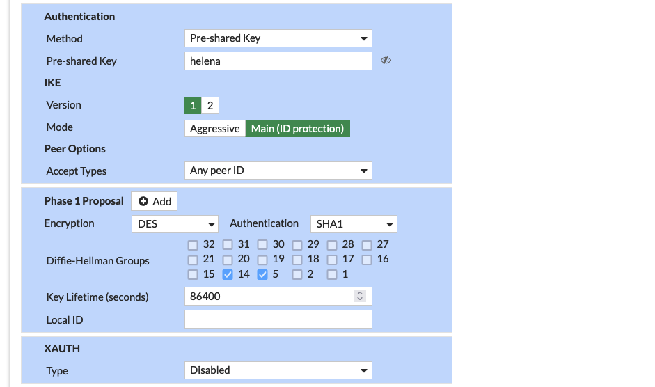
Configure the Pre-shared Key and Phase 1 Proposal as needed
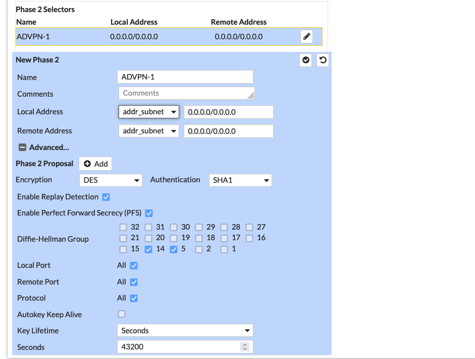
Same goes with the Phase 2 Proposal
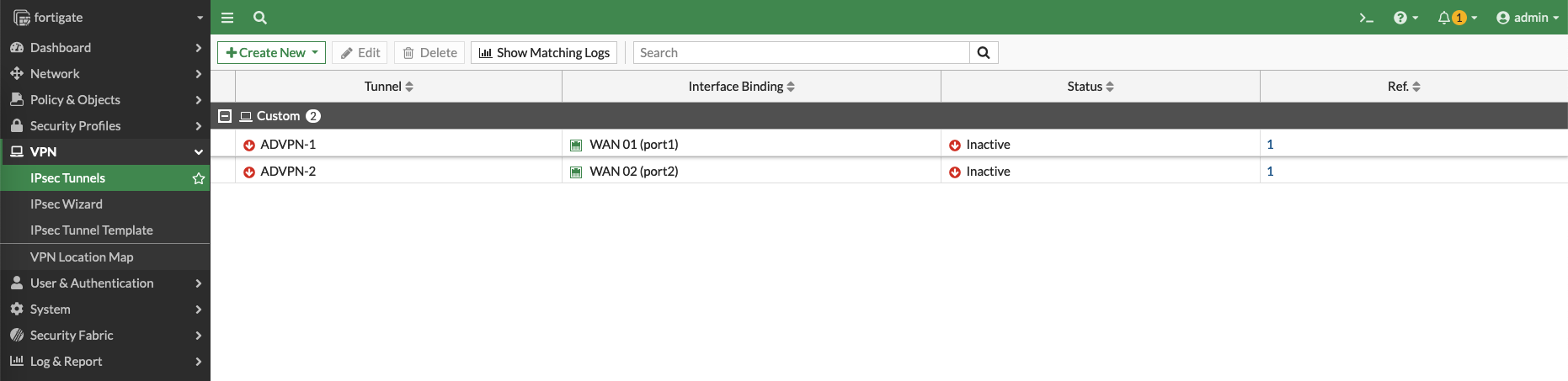
Repeat the process for WAN 2 Interface and we end up with these 2 VPN Connections
Next we configure the SD-WAN Zone having two members of the IPSec VPNs just created

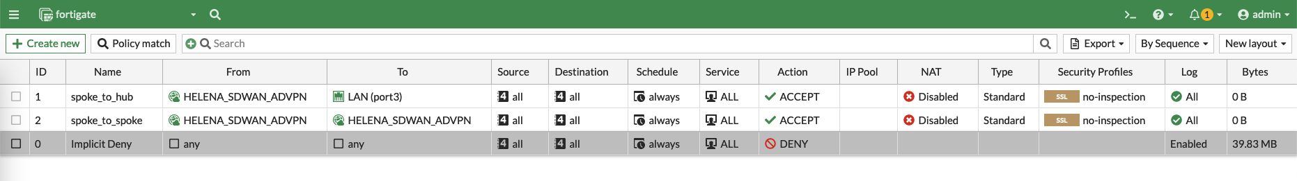
After that create two Policies to allow traffic from spokes to hub and between the spokes
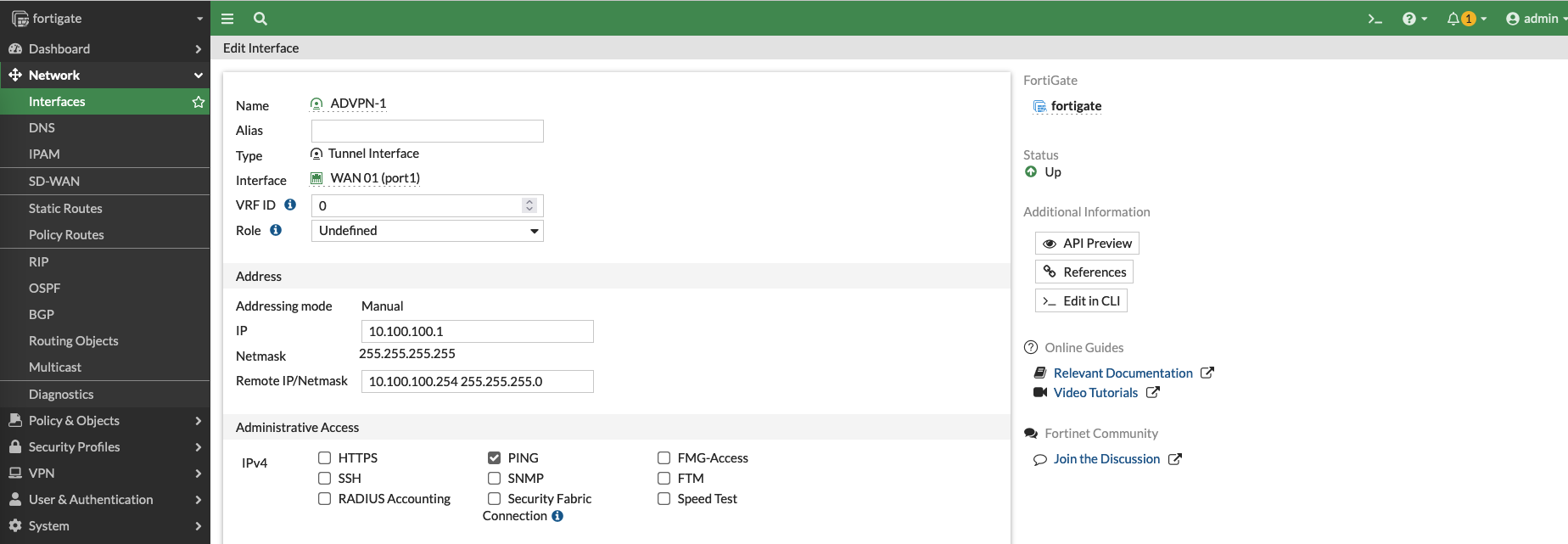
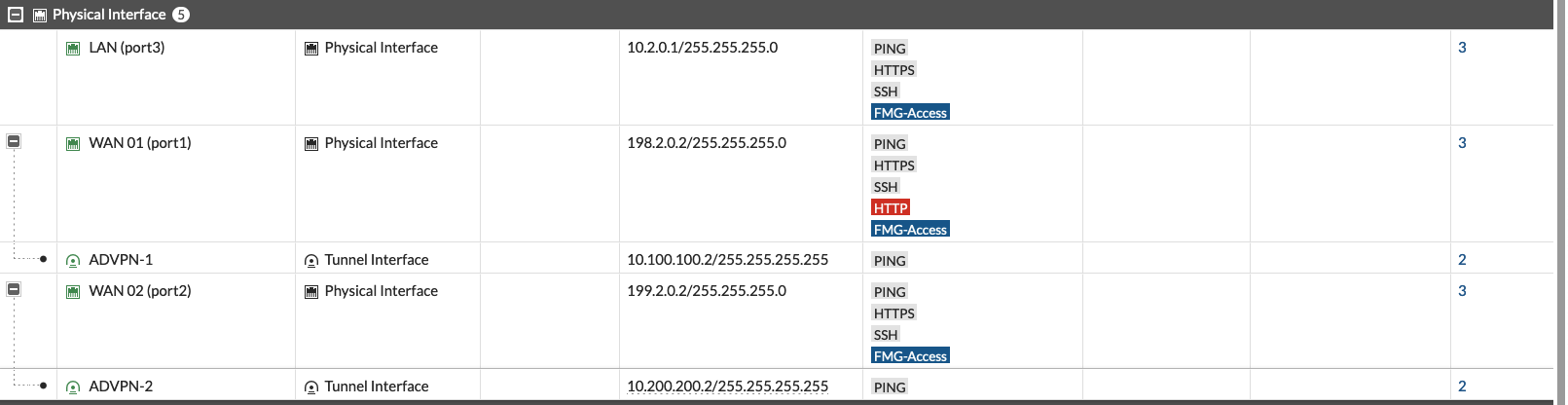
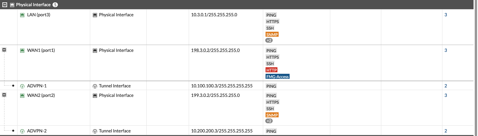
On the VPN 1 Interface, add an IP Address that’ll be used by BGP
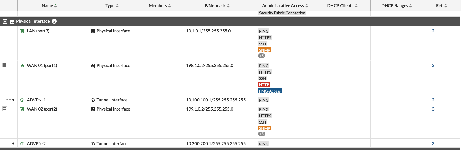
Do the same for VPN 2

Here’s what we end up with on the Interface Configuration
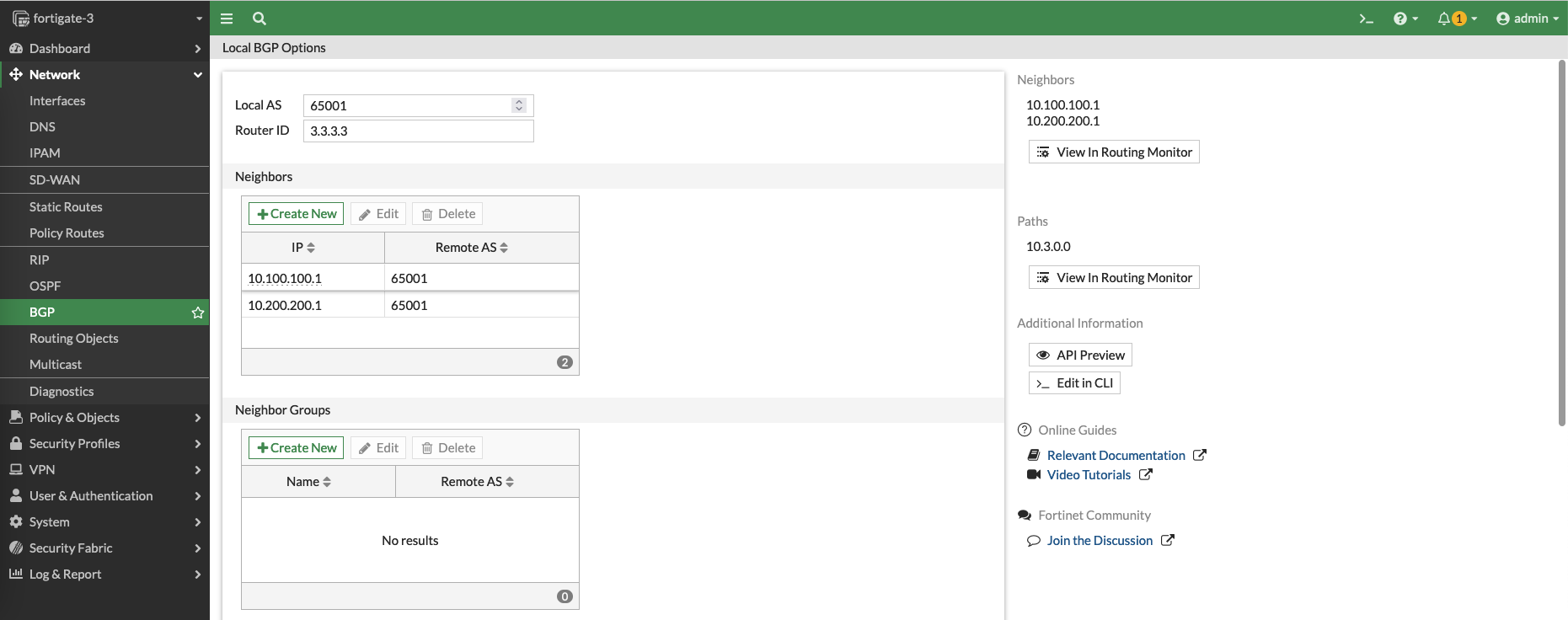
Lastly, configure BGP as the Overlay Routing Protocol for SD-WAN.
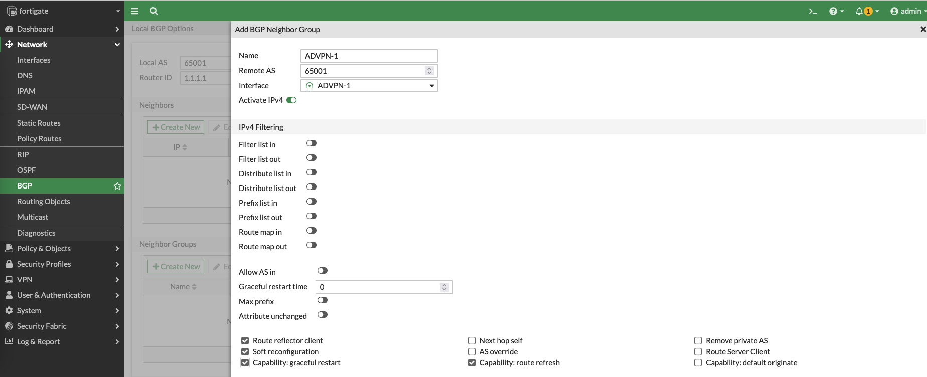
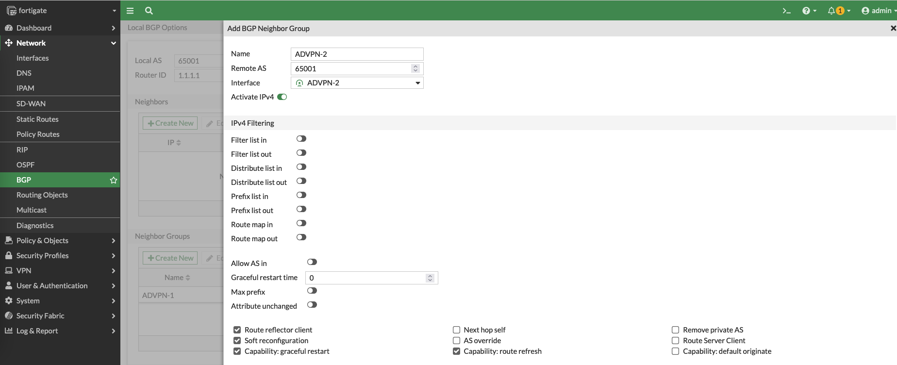
set the Local AS to be 65001 and add a neighbor group containing the VPN 1 interface, make sure to enable the Route reflector client
Same goes with the second VPN interface
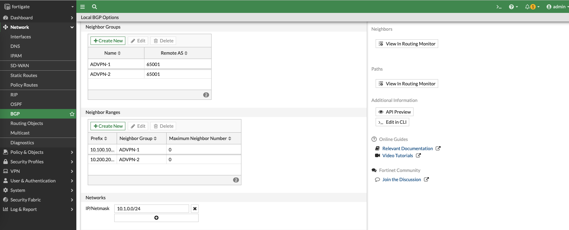
Next create a BGP Neighbor Range containing the network subnet of the VPN 1 interface
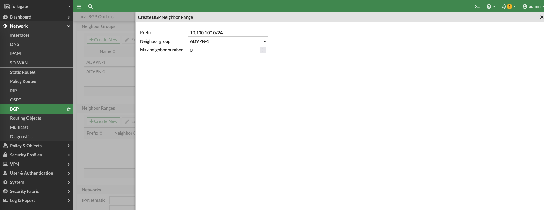
Add another one for the VPN 2 interface

And finally add the Local subnet, and hit save
Configuring the Spoke on Site 2
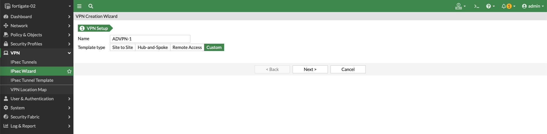
Create a IPSec VPN for interface WAN 1
Configure the Remote Gateway going out to the Hub WAN 1 interface, disable Add Route and enable Auto Discovery Receiver
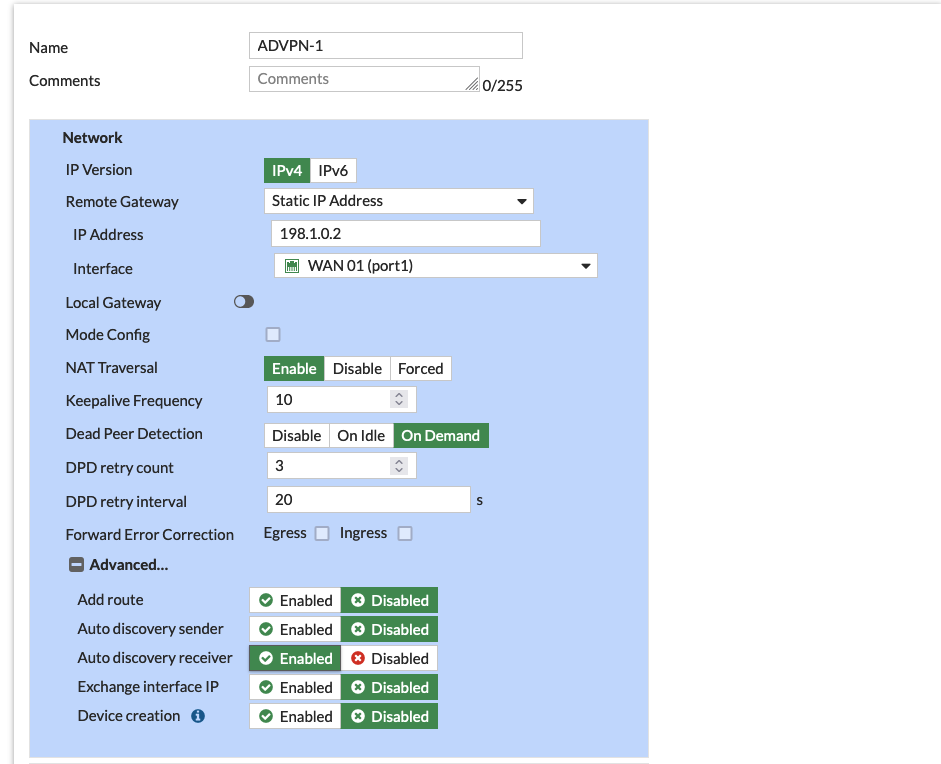
- When the Hub with Auto Discovery Sender sends out discovery messages to identify compatible peers, the Auto Discovery Receiver listens for these messages. When a compatible peer is found, the Auto Discovery Receiver can initiate the negotiation process for setting up a secure IPSec VPN tunnel between the two devices.
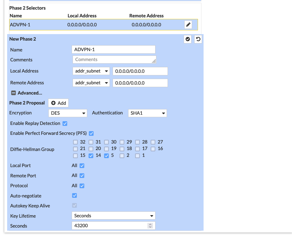
Configure the Pre-shared Key and Phase 1 Proposal as needed

Same goes with the Phase 2 Proposal
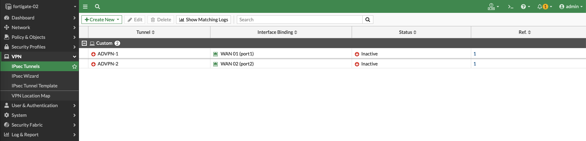
Repeat the process for the WAN 2 interface, and this is what we end up with
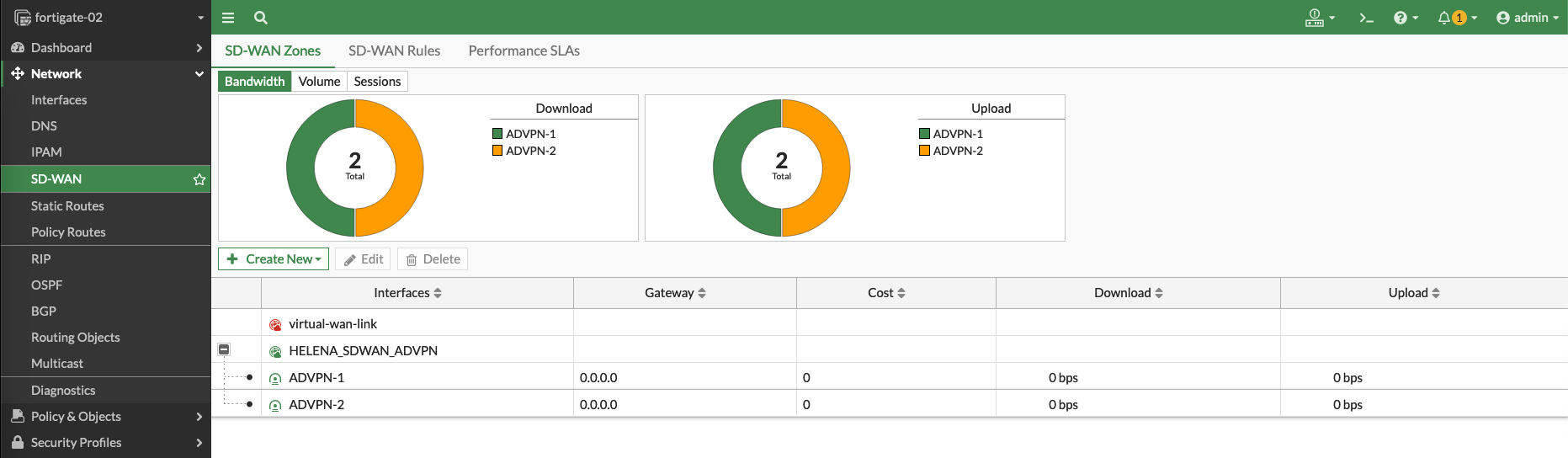
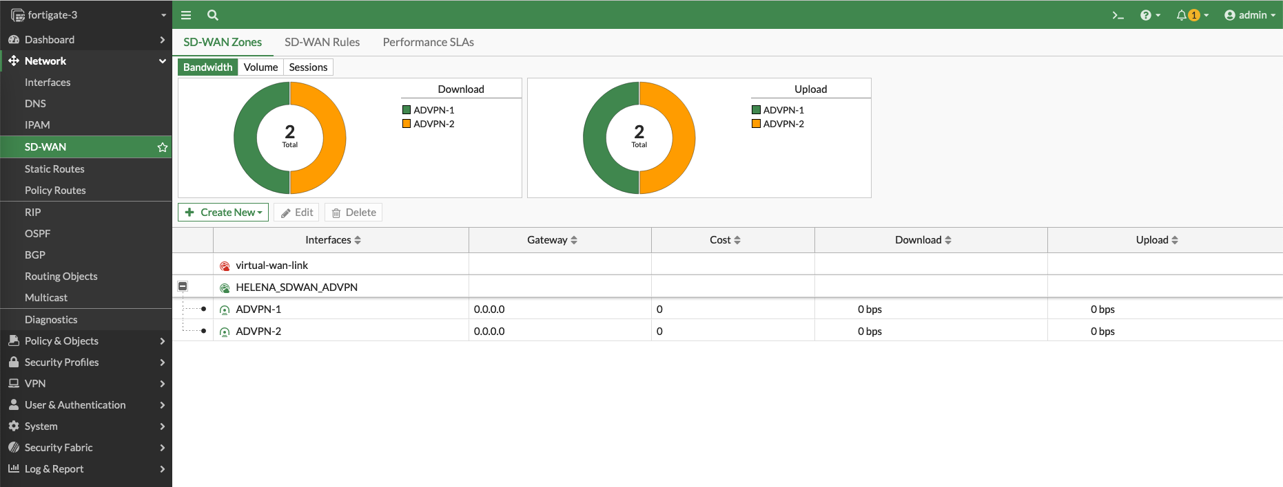
Next, create an SD-WAN Zone containing these 2 VPNs as the members
Create two Policies to allow traffic going in and out of the SD-WAN interface

After that, configure the VPN Interfaces with IP Addresses to be used by BGP
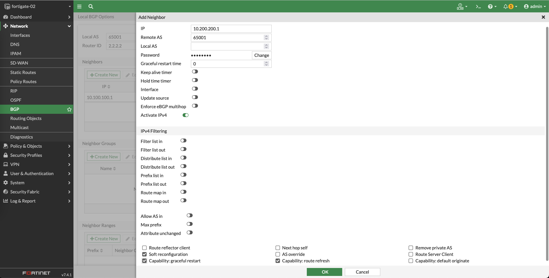
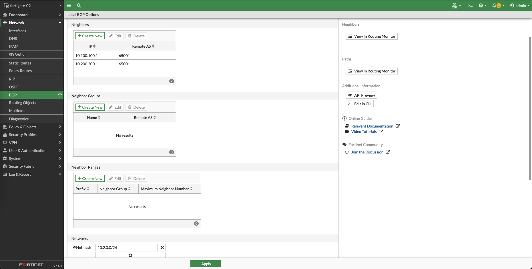
And configure the BGP with the same AS number of 65001, here we add a neighbor of the Hub WAN 1 interface

Add the second neighbor for Hub’s WAN 2 interface
Lastly add the Local subnet, and hit save
Configuring the Spoke on Site 3
On the Spoke on Site 3, the configuration is nearly identical with the Spoke on Site 2
Validating the Configuration
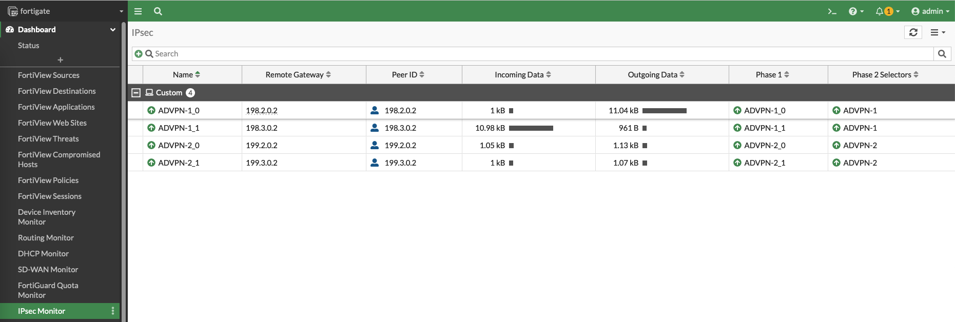
On Hub, we can see the IPSec VPNs have been automatically established to the spokes
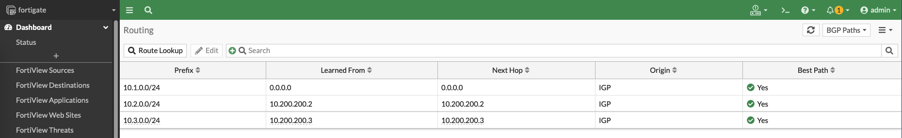
And on Routing Monitors, we can see all spokes’ VPN interfaces as the BGP Neighbors

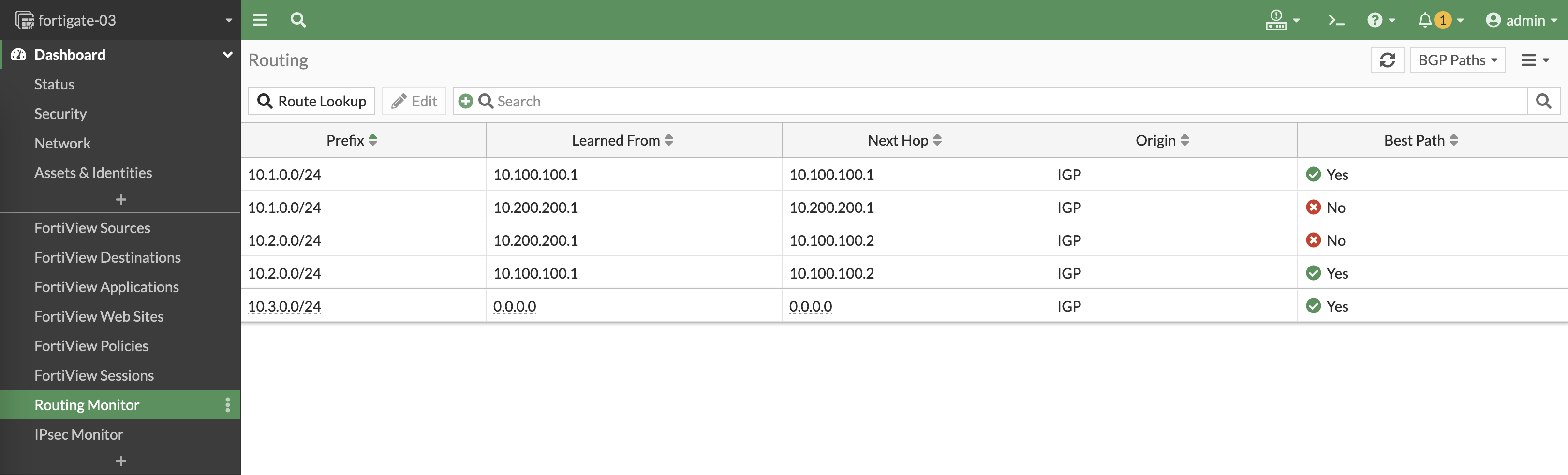
And on BGP Paths, we can also see the local subnets of the spokes being advertised by BGP

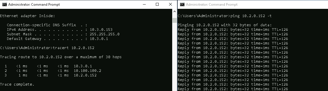
On the client PC on Site 2, testing with ping proves that the connectivity is up going to the Site 3
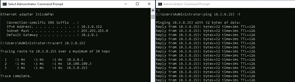
Same goes with the other way around
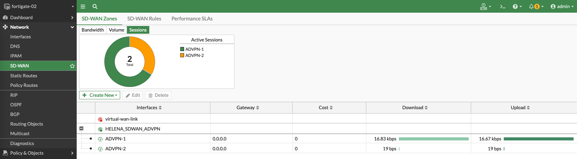
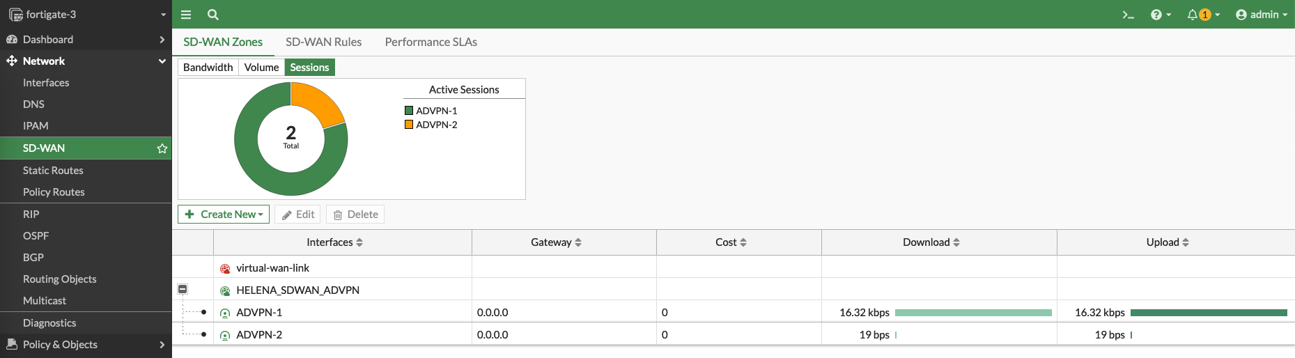
And on the Spokes, the VPN utilizations can be observed as the traffic flowing through the SD-WAN
Enable ECMP on BGP
ECMP (Equal-Cost Multi-Path) is a routing technique that allows multiple paths with the same cost to be used simultaneously for load balancing
Right now if we take a look at the BGP Paths, we have multiple paths to reach the local subnets on other sites but only one being used
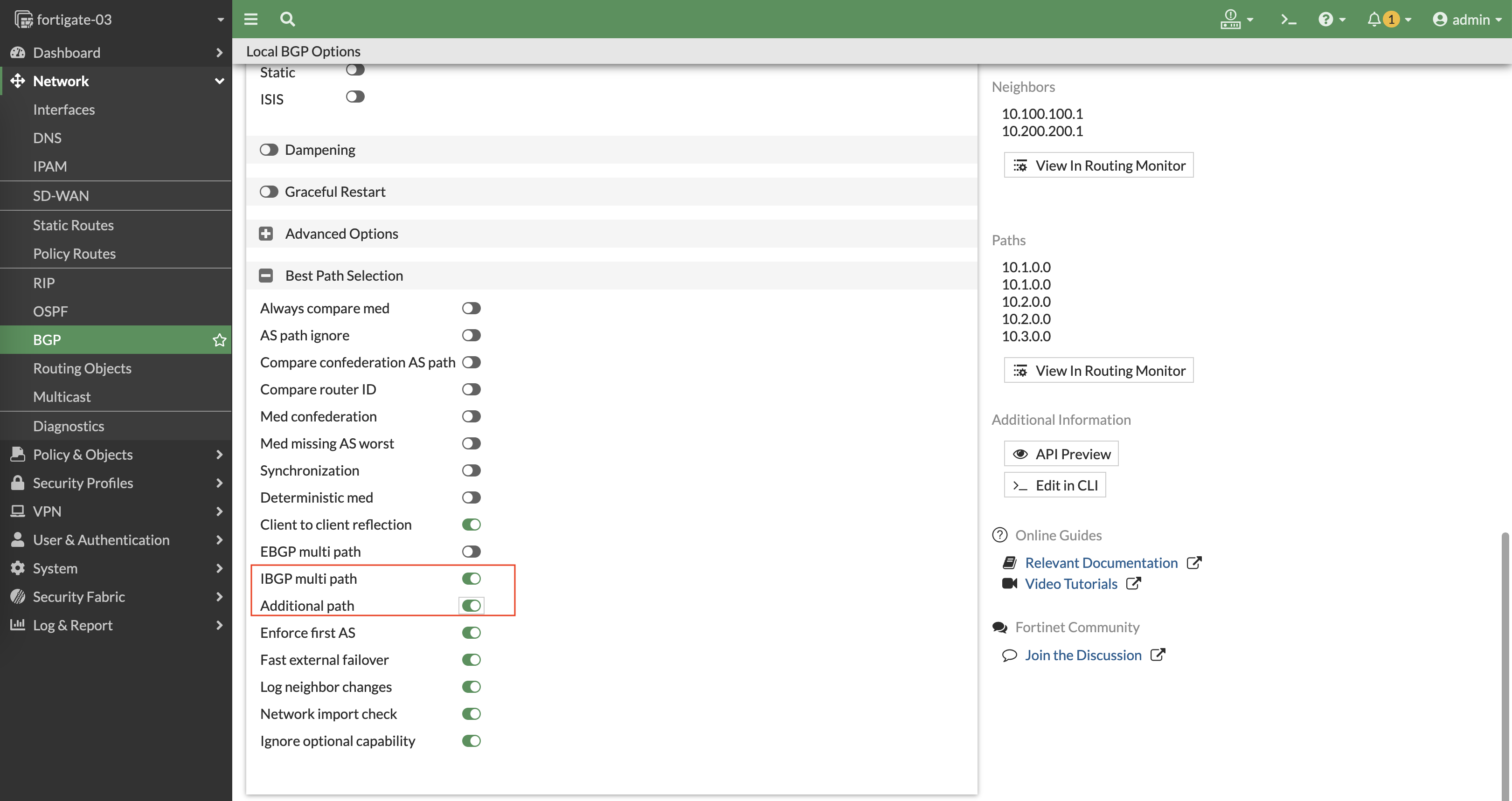
To enable ECMP, go to BGP configuration and enable IBGP Multipath and Additional Path
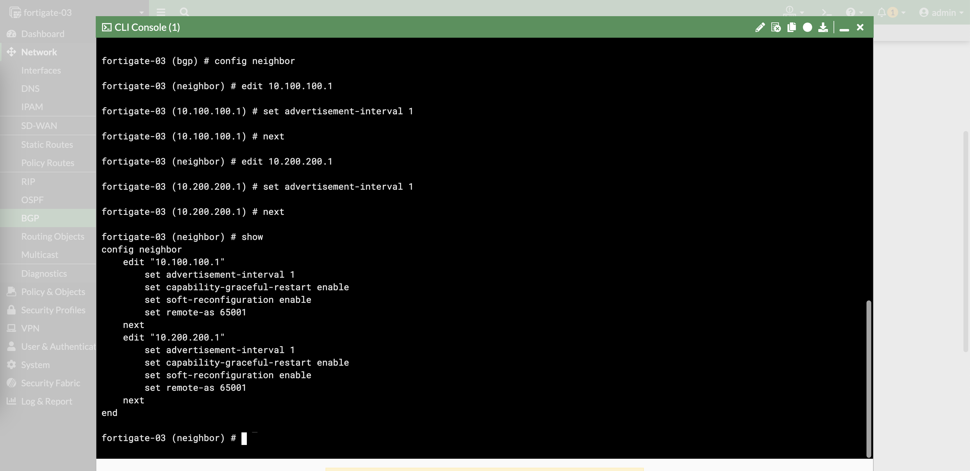
Additionally on CLI, we can also lower the advertisement interval to 1 second
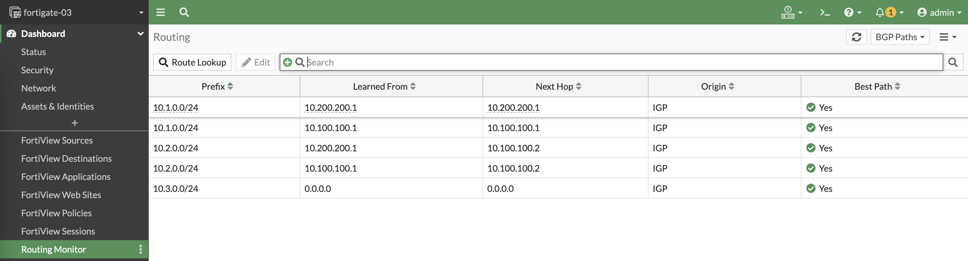
Apply the config on all nodes and now all the available paths can and will be utilized
Configuring Performance SLA on Hub
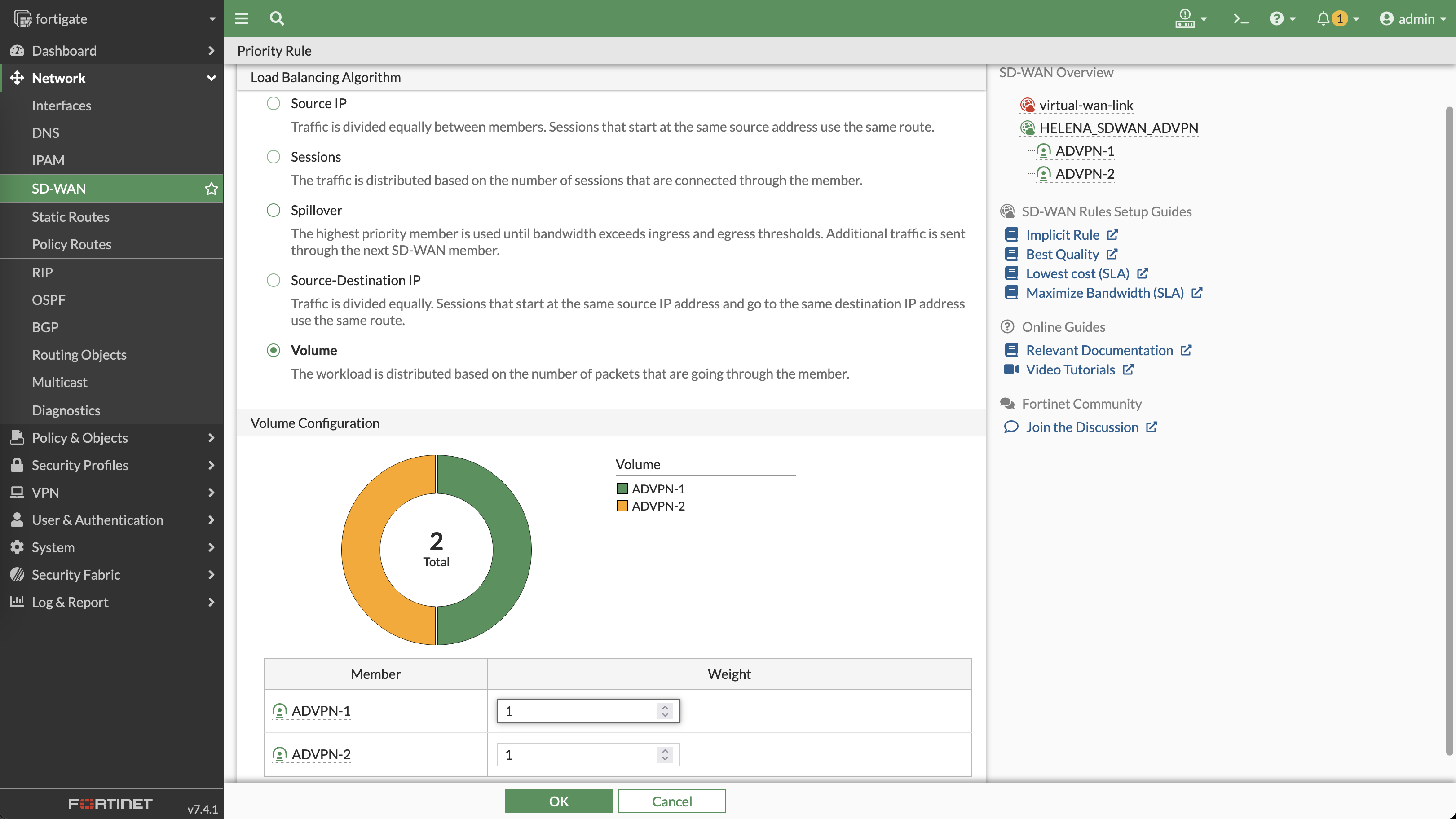
To also enable load balancing on SD-WAN VPN Tunnel, use Volume based priority rules
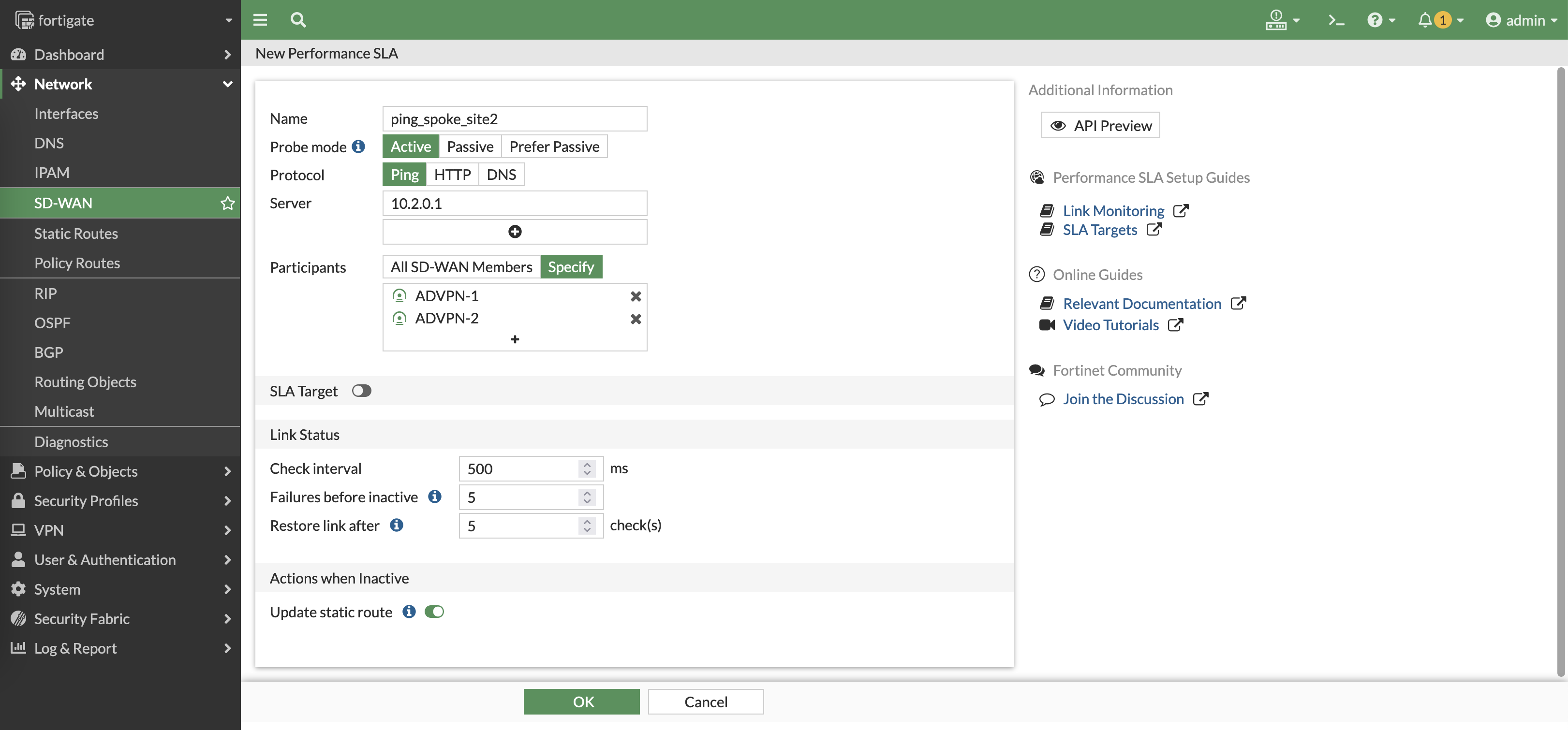
Create a performance SLA that continuously doing ping to the local subnet of site 2
Do the same to do ping to site 3
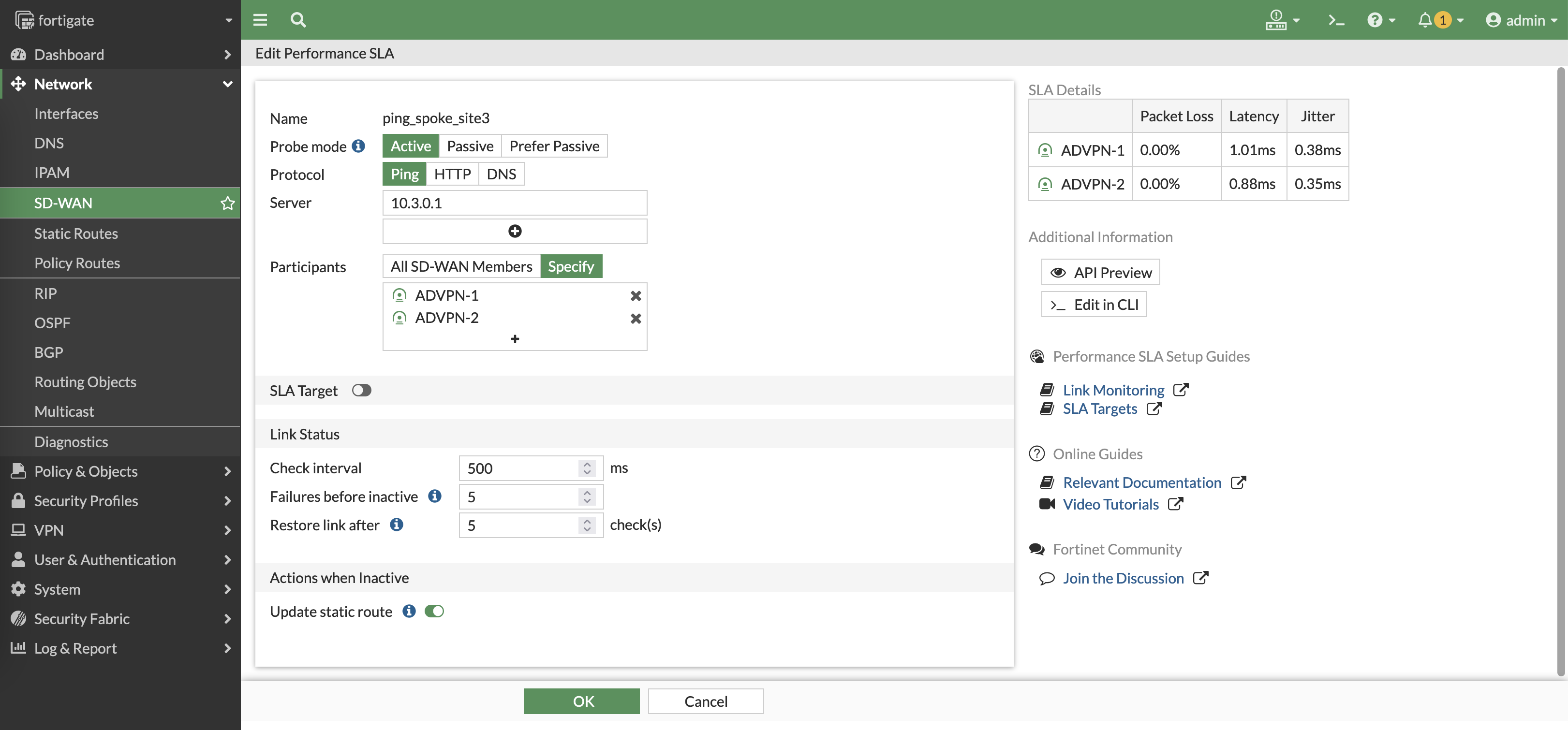
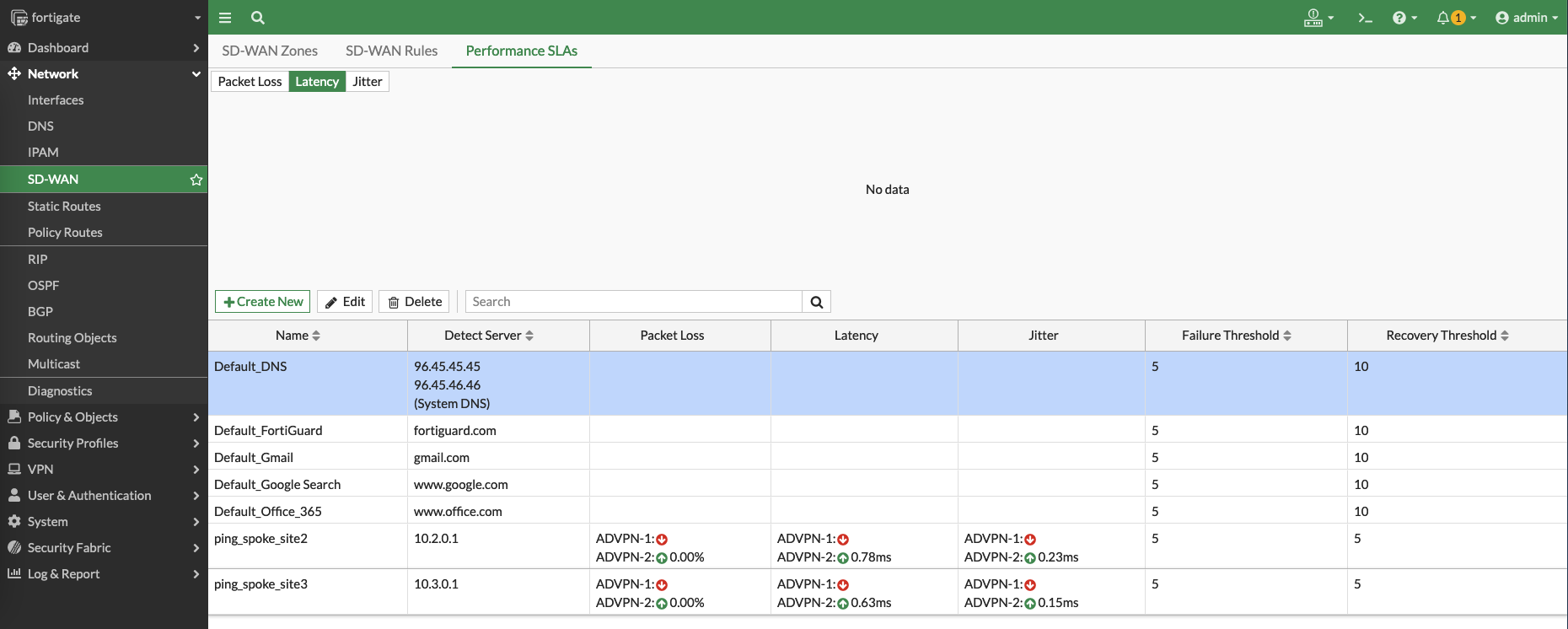
Now we have 2 performance SLAs to measure latency to both sites

Additionaly, we can set the SD-WAN Members to use the source of the local subnet to measure latency

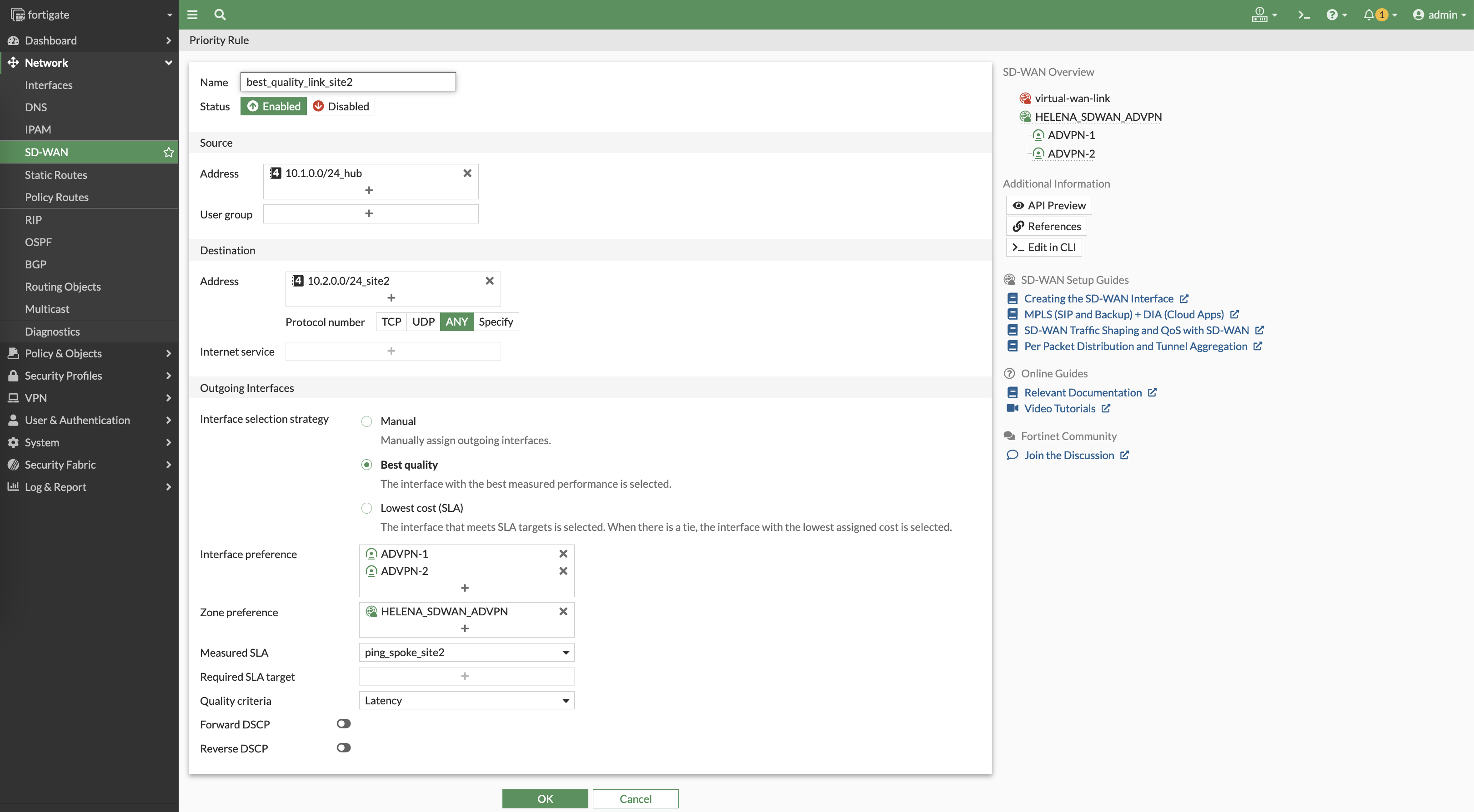
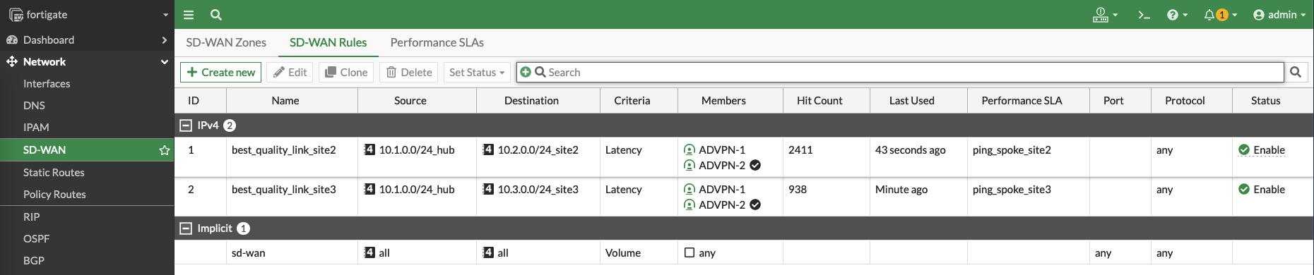
Next we create a new priority rule to utilize the performance SLA made to make judgement to use the lowest latency for the SD-WAN traffic to site 2
Do the same for site 3
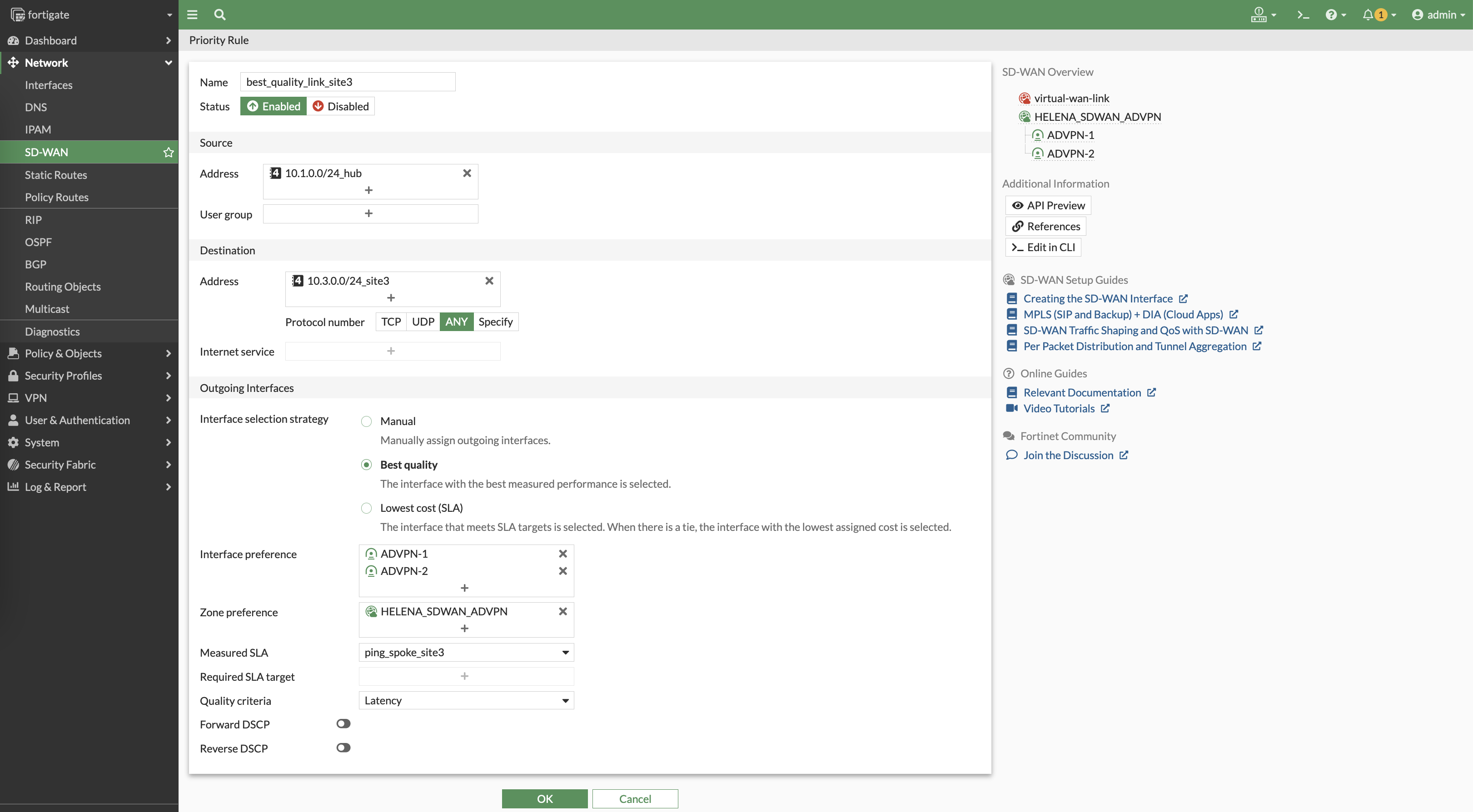
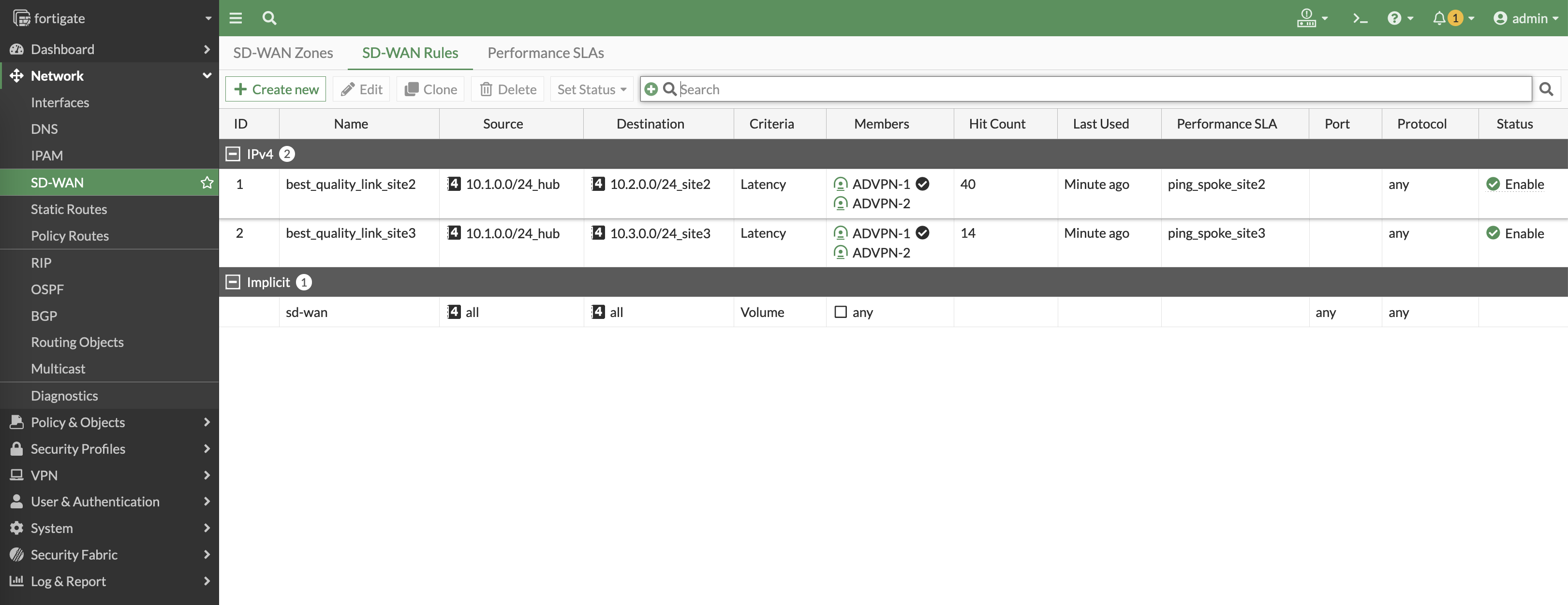
Here we can see the rules determine which VPN has the best latency to reach the sites, and will continuously measure the latency to make sure the best path is used
Configuring Performance SLA on Spoke Sites
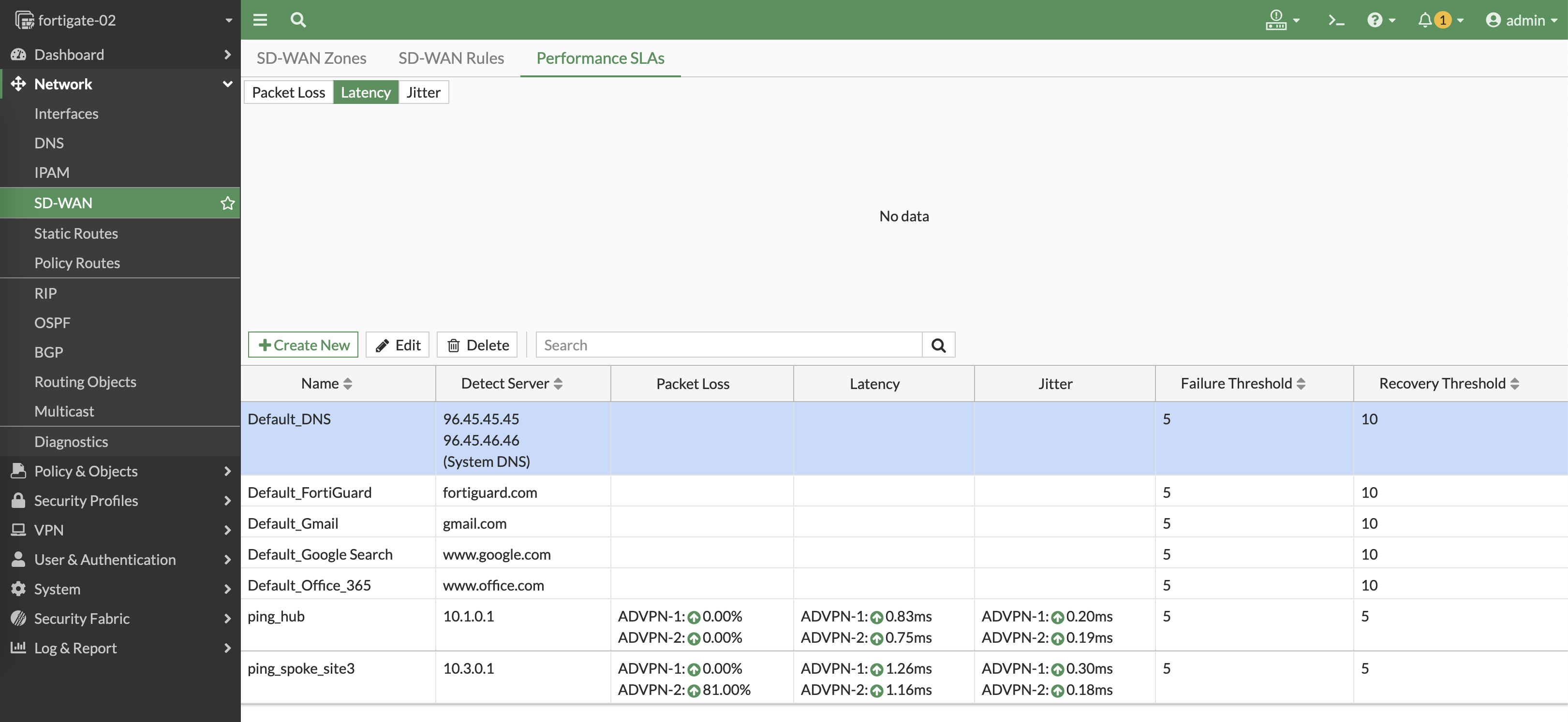
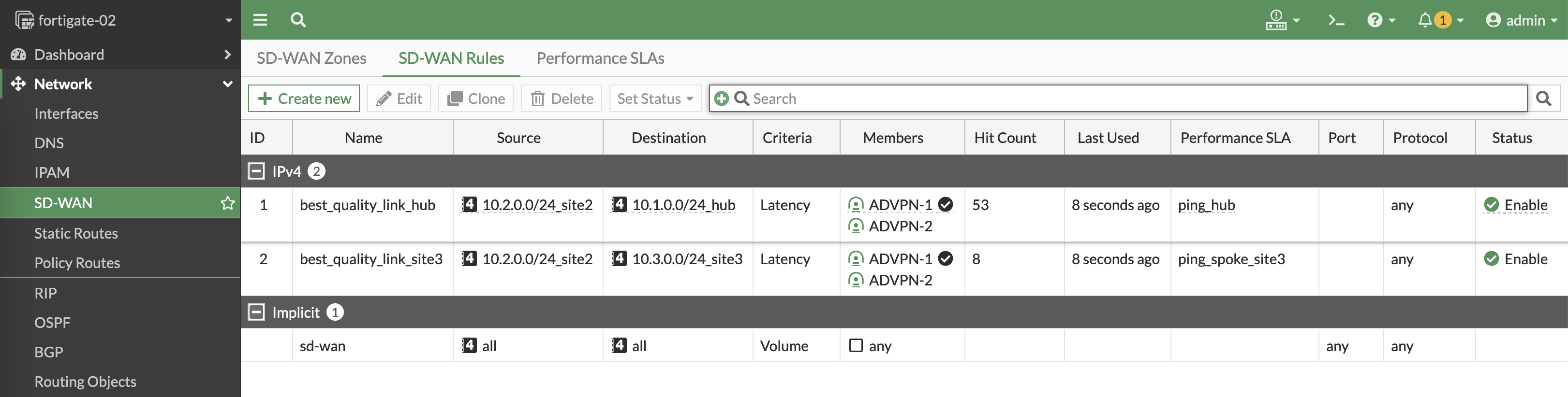
Configuration is pretty much the same, but on sites the SLA is made going to Hub and Other Site
Site 2
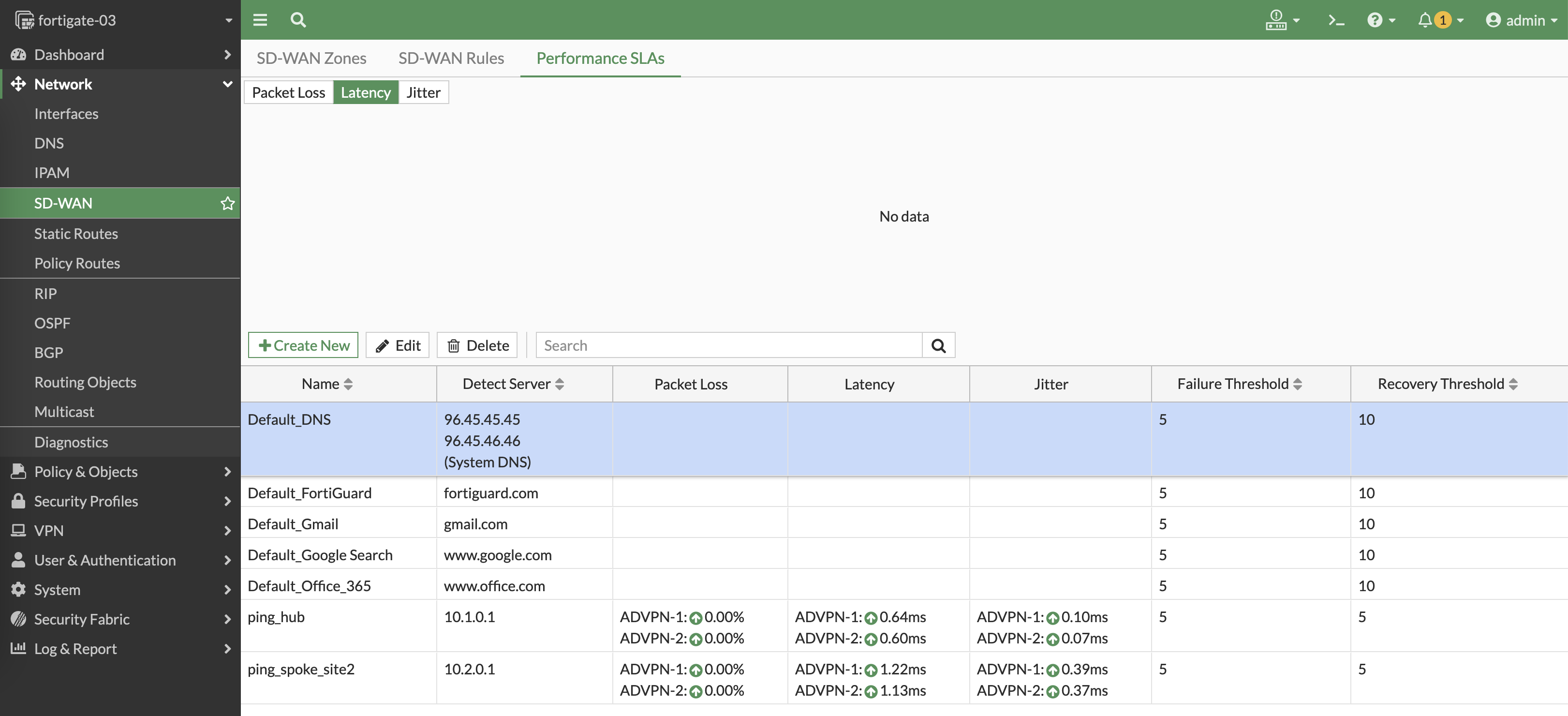
Site 3

Testing the Performance SLA
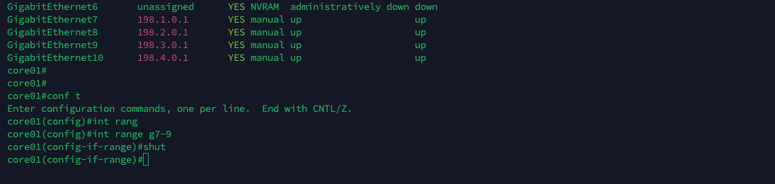
Now we’re gonna shutdown the ISP 1 network
And on the Performanc SLA, we can see VPN 1 network is detected to be down
And the rules will redirect all traffic to use the VPN 2 network
Looking over at the BGP Paths, we can also observe that the only paths remaining in the table are the ones going to the ISP 2 network