MPLS with MP-BGP
What is MPLS?
MPLS, or Multiprotocol Label Switching, is a networking technology that enhances the efficiency and performance of data packet routing. It is done by assigning labels to packets, allowing routers to quickly determine how to forward them along predefined paths using the known “label-switched paths.”
MPLS is widely used on Internet Service Provider (ISP) networks.
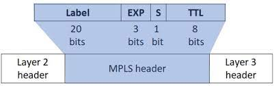
- Label: The label is a short identifier assigned to the packet by the ingress router (the router that initially enters the MPLS network). It represents the path the packet should take through the network. Routers along the path use this label to make forwarding decisions.
- Exp (Experimental) bits: These bits were originally intended for experimental purposes but are often used for Quality of Service (QoS) markings.
- S (Bottom of Stack) bit: This bit indicates whether the current label is the last in the stack. MPLS can stack labels, creating a hierarchical label structure for more complex routing scenarios.
- TTL (Time-to-Live) field: Similar to the TTL field in IP headers, this field limits the lifespan of a packet within the network.
What is MP-BGP?
MP-BGP, or Multiprotocol Border Gateway Protocol, is an extension of the Border Gateway Protocol (BGP) designed to support the exchange of routing information for multiple protocols.
MP-BGP extends the capabilities of traditional BGP by allowing it to carry and distribute routing information for different network protocols within the same BGP session.
Network Topology
Here’s the topology for this deployment
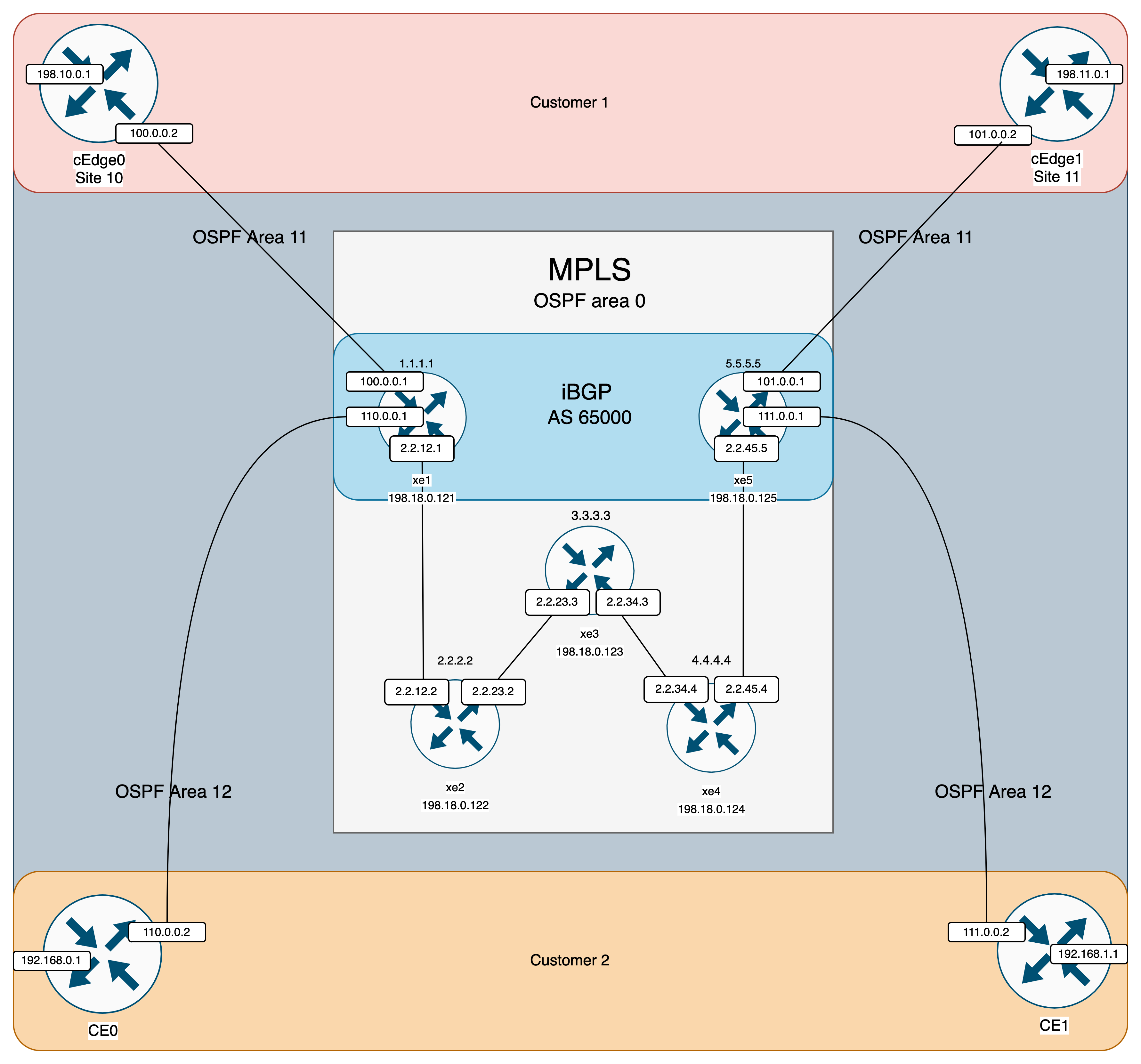
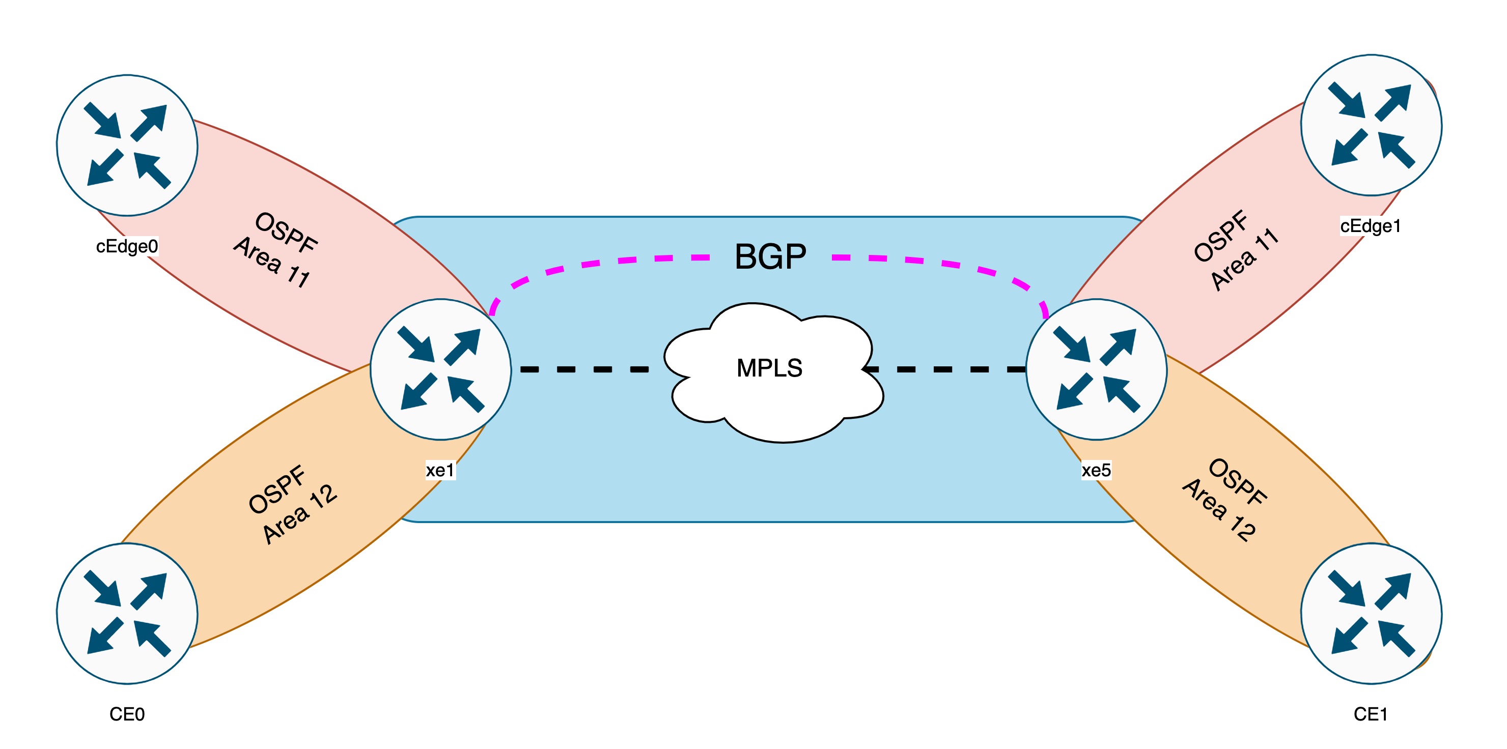
We have 5 Routers running MPLS where router xe1 and xe5 will become the PE (Provider Edge), meaning it’ll be the connecting router to the Customer’s router (CE or Customer Edge), which will be the cEdge0 & cEdge1 for Customer 1 and CE0 & CE1 for Customer 2.
MPLS will be run on top of OSPF area 0 and iBGP will redistribute the network between 2 PE’s.
Configuring Interfaces
First lets give each of them appropriate IP Addressing following the Topology
XE1
1
2
3
4
Interface              IP-Address      OK? Method Status                Protocol
GigabitEthernet1       198.18.0.121    YES manual up                    up
GigabitEthernet2       2.2.12.1        YES manual up                    up
Loopback0              1.1.1.1         YES manual up                    up
XE2
1
2
3
4
5
Interface              IP-Address      OK? Method Status                Protocol
GigabitEthernet1       198.18.0.122    YES manual up                    up
GigabitEthernet2       2.2.12.2        YES manual up                    up
GigabitEthernet3       2.2.23.2        YES manual up                    up
Loopback0              2.2.2.2         YES manual up                    up
XE3
1
2
3
4
5
Interface              IP-Address      OK? Method Status                Protocol
GigabitEthernet1       198.18.0.123    YES manual up                    up
GigabitEthernet2       2.2.23.3        YES manual up                    up
GigabitEthernet3       2.2.34.3        YES manual up                    up
Loopback0              3.3.3.3         YES manual up                    up
XE4
1
2
3
4
5
Interface              IP-Address      OK? Method Status                Protocol
GigabitEthernet1       198.18.0.124    YES manual up                    up
GigabitEthernet2       2.2.34.4        YES manual up                    up
GigabitEthernet3       2.2.45.4        YES manual up                    up
Loopback0              4.4.4.4         YES manual up                    up
XE5
1
2
3
4
Interface              IP-Address      OK? Method Status                Protocol
GigabitEthernet1       198.18.0.125    YES manual up                    up
GigabitEthernet2       2.2.45.5        YES manual up                    up
Loopback0              5.5.5.5         YES manual up                    up
Configuring OSPF
Next we configure OSPF so all the routers can communicate with each other
Run this command on all the routers
1
2
router ospf 1
 network 2.2.0.0 0.0.255.255 area 0
Running this command will show that all routers have joined the OSPF area 0 network and able to see each other
1
2
3
4
5
6
7
8
9
10
11
12
13
14
15
16
17
18
19
20
xe1#show ip ospf database

            OSPF Router with ID (1.1.1.1) (Process ID 1)

                Router Link States (Area 0)

Link ID         ADV Router      Age         Seq#       Checksum Link count
1.1.1.1         1.1.1.1         215         0x80000014 0x003AA5 2
2.2.2.2         2.2.2.2         225         0x80000017 0x00B5CE 3
3.3.3.3         3.3.3.3         240         0x8000000F 0x00153B 3
4.4.4.4         4.4.4.4         176         0x8000000F 0x004EC6 3
5.5.5.5         5.5.5.5         185         0x8000000C 0x002A45 2

                Net Link States (Area 0)

Link ID         ADV Router      Age         Seq#       Checksum
2.2.12.2        2.2.2.2         225         0x80000001 0x000F05
2.2.23.3        3.3.3.3         279         0x80000001 0x00C13A
2.2.34.4        4.4.4.4         247         0x80000001 0x00746F
2.2.45.4        4.4.4.4         193         0x80000001 0x005F71
Running show ip route command on XE1 shows that XE5 has been learned through OSPF
1
2
3
4
5
6
7
xe1#show ip route 5.5.5.5
Routing entry for 5.5.5.5/32
  Known via "ospf 1", distance 110, metric 5, type intra area
  Last update from 2.2.12.2 on GigabitEthernet2, 00:03:40 ago
  Routing Descriptor Blocks:
  * 2.2.12.2, from 5.5.5.5, 00:03:40 ago, via GigabitEthernet2
      Route metric is 5, traffic share count is 1
Running traceroute also shows all the hops along the OSPF network used to get to XE5
1
2
3
4
5
6
7
xe1#traceroute 5.5.5.5
Tracing the route to 5.5.5.5
VRF info: (vrf in name/id, vrf out name/id)
  1 2.2.12.2 1 msec 1 msec 1 msec
  2 2.2.23.3 1 msec 1 msec 1 msec
  3 2.2.34.4 1 msec 1 msec 1 msec
  4 2.2.45.5 2 msec *  3 msec
Configuring MPLS
To configure MPLS, all we need to do is enable LDP Autoconfig under OSPF Router process on all routers.
1
2
router ospf 1
 mpls ldp autoconfig
- LDP (Label Distribution Protocol) is a protocol used within MPLS networks to establish and manage the distribution of labels that are used for forwarding data packets along label-switched paths.
- LDP Autoconfig is a feature in MPLS networks that automates the process of distributing labels and setting up label-switched paths without manual configuration.
Running show mpls ldp neighbor on any of ther router will show all the MPLS neighbors
1
2
3
4
5
xe1#show mpls ldp neighbor | i Peer
    Peer LDP Ident: 198.18.0.122:0; Local LDP Ident 198.18.0.121:0
    Peer LDP Ident: 198.18.0.123:0; Local LDP Ident 198.18.0.121:0
    Peer LDP Ident: 198.18.0.124:0; Local LDP Ident 198.18.0.121:0
    Peer LDP Ident: 198.18.0.125:0; Local LDP Ident 198.18.0.121:0
And now if we try doing a traceroute from XE1 to XE5, we’ll see MPLS in action
1
2
3
4
5
6
7
xe1#traceroute 5.5.5.5
Tracing the route to dynamic-005-005-005-005.5.5.pool.telefonica.de (5.5.5.5)
VRF info: (vrf in name/id, vrf out name/id)
  1 2.2.12.2 [MPLS: Label 18 Exp 0] 3 msec 2 msec 1 msec
  2 2.2.23.3 [MPLS: Label 18 Exp 0] 2 msec 2 msec 2 msec
  3 2.2.34.4 [MPLS: Label 18 Exp 0] 2 msec 2 msec 2 msec
  4 2.2.45.5 2 msec *  3 msec
- in this traceroute, XE4 (2.2.34.4) acts as the “penultimate hop” which means the second last hop of the MPLS route, thus it performs the label removal (popping) before the packet is sent into the next network segment, resulting the next hop no longer uses MPLS
Configuring iBGP
BGP plays a crucial role in MPLS networks by enabling the exchange of routing information and facilitating the establishment of Label Switched Paths (LSPs).
BGP facilitates the redistribution of customer’s segment across the MPLS network, enabling their network segments to be visible on each other.
Now we configure Internal BGP connecting XE1 and XE5
XE1
1
2
3
4
5
6
router bgp 65000
 neighbor 5.5.5.5 remote-as 65000
 neighbor 5.5.5.5 update-source Loopback 0
 no auto-summary
 address-family vpnv4
 neighbor 5.5.5.5 activate
XE5
1
2
3
4
5
6
router bgp 65000
 neighbor 1.1.1.1 remote-as 65000
 neighbor 1.1.1.1 update-source Loopback 0
 no auto-summary
 address-family vpnv4
 neighbor 1.1.1.1 activate
- no auto-summary: This command disables the automatic summarization of BGP network routes.
- address-family vpnv4: VPNv4 is used to carry VPN routing information. It creates a VPN connection between XE1 and XE5, rather than traditional IPv4 routing if the 2 routers were adjacent.
Running command “show bgp vpnv4 unicast all summary” shows the BGP neighbors
1
2
3
4
5
6
xe1#show ip bgp summary
BGP router identifier 1.1.1.1, local AS number 65000
BGP table version is 1, main routing table version 1

Neighbor        V           AS MsgRcvd MsgSent   TblVer  InQ OutQ Up/Down  State/PfxRcd
5.5.5.5         4        65000       0       0        1    0    0 never    Idle
Configuring VRF (Virtual Routing and Forwarding)
The cool thing about MPLS is its ability to serve multiple customers and segregate their networks with one MPLS deployment. This is done using VRF.
VRF is a technology that creates isolated routing environments within a single network device. It lets different groups or services use the same hardware while keeping their networks separate and secure.
Next we’ll create VRF on XE1 and XE5 pointing to its respective CE router.
First, we create VRF for Customer 1 and Customer 2 on XE1
XE1
1
2
3
4
5
6
7
ip vrf CUST-1
 rd 1:1
 route-target both 1:1

ip vrf CUST-2
 rd 2:2
 route-target both 2:2
- ip vrf CUST-1: This command creates a VRF named “CUST-1.”
- rd 1:1: This command sets the Route Distinguisher (RD) for the “CUST-1” VRF. The RD is a unique identifier used in MPLS-based VPNs to distinguish routes from different VPNs.
- route-target both 1:1: This command configures the Route Target (RT) for the “CUST-1” VRF. The RT is used to control the import and export of routes between different VRFs.
Now associate the Interface to each Customer VRF
1
2
3
4
5
6
7
8
9
10
11
interface GigabitEthernet 3
 no shutdown
 ip vrf forwarding CUST-1
 ip address 100.0.0.1 255.255.255.0
 ip ospf 11 area 11

interface GigabitEthernet 4
 no shutdown
 ip vrf forwarding CUST-2
 ip address 110.0.0.1 255.255.255.0
 ip ospf 12 area 12
Now we have 2 additional IP Routing tables for VRF Customer 1 and 2
1
2
3
4
5
6
7
8
9
10
11
12
13
xe1#show ip route vrf CUST-1
Gateway of last resort is not set

      100.0.0.0/8 is variably subnetted, 2 subnets, 2 masks
C        100.0.0.0/24 is directly connected, GigabitEthernet3
L        100.0.0.1/32 is directly connected, GigabitEthernet3

xe1#show ip route vrf CUST-2
Gateway of last resort is not set

      110.0.0.0/8 is variably subnetted, 2 subnets, 2 masks
C        110.0.0.0/24 is directly connected, GigabitEthernet4
L        110.0.0.1/32 is directly connected, GigabitEthernet4
Now we try pinging them
1
2
3
4
5
6
7
8
9
10
11
xe1#ping vrf CUST-1 100.0.0.2
Type escape sequence to abort.
Sending 5, 100-byte ICMP Echos to 100.0.0.2, timeout is 2 seconds:
!!!!!
Success rate is 100 percent (5/5), round-trip min/avg/max = 1/1/2 ms

xe1#ping vrf CUST-2 110.0.0.2
Type escape sequence to abort.
Sending 5, 100-byte ICMP Echos to 110.0.0.2, timeout is 2 seconds:
!!!!!
Success rate is 100 percent (5/5), round-trip min/avg/max = 1/1/2 ms
Then repeat these steps on the other side of the topology for XE5
XE5
1
2
3
4
5
6
7
ip vrf CUST-1
 rd 1:1
 route-target both 1:1

ip vrf CUST-2
 rd 2:2
 route-target both 2:2
1
2
3
4
5
6
7
8
9
10
11
interface GigabitEthernet 3
 no shutdown
 ip vrf forwarding CUST-1
 ip address 101.0.0.1 255.255.255.0
 ip ospf 11 area 11

interface GigabitEthernet 4
 no shutdown
 ip vrf forwarding CUST-2
 ip address 111.0.0.1 255.255.255.0
 ip ospf 12 area 12
Configuring Route Redistribution for BGP and OSPF
So far, we have configured OSPF between PE and CE, we also have configured BGP between PE (XE1 and XE5) running over MPLS.
Now we need to redistribute the routes between these 2 routing protocols so the routing tables are shared and ultimately each customer’s router can communicate with each other.
First, lets redistribute OSPF on BGP.
Run this command on both PE (XE1 and XE5)
1
2
3
4
5
router bgp 65000
 address-family ipv4 vrf CUST-1
  redistribute ospf 11
 address-family ipv4 vrf CUST-2
  redistribute ospf 12
Now if we run the command “show ip bgp vpnv4 all”, we can see OSPF routes being discovered by BGP
XE1
1
2
3
4
5
6
7
8
9
     Network          Next Hop            Metric LocPrf Weight Path
Route Distinguisher: 1:1 (default for vrf CUST-1)
 *>   100.0.0.0/24     0.0.0.0                  0         32768 ?
 *>i  101.0.0.0/24     5.5.5.5                  0    100      0 ?
Route Distinguisher: 2:2 (default for vrf CUST-2)
 *>   110.0.0.0/24     0.0.0.0                  0         32768 ?
 *>i  111.0.0.0/24     5.5.5.5                  0    100      0 ?
 *>   192.168.0.1/32   110.0.0.2                2         32768 ?
 *>i  192.168.1.1/32   5.5.5.5                  2    100      0 ?
XE5
1
2
3
4
5
6
7
8
Route Distinguisher: 1:1 (default for vrf CUST-1)
 *>i  100.0.0.0/24     1.1.1.1                  0    100      0 ?
 *>   101.0.0.0/24     0.0.0.0                  0         32768 ?
Route Distinguisher: 2:2 (default for vrf CUST-2)
 *>i  110.0.0.0/24     1.1.1.1                  0    100      0 ?
 *>   111.0.0.0/24     0.0.0.0                  0         32768 ?
 *>i  192.168.0.1/32   1.1.1.1                  2    100      0 ?
 *>   192.168.1.1/32   111.0.0.2                2         32768 ?
Now we need the CE to see each other’s OSPF routes through BGP, so lets redistribute BGP on OSPF.
Run this command
1
2
3
4
router ospf 11
 redistribute bgp 65000
router ospf 12
 redistribute bgp 65000
Now if we take a look at CE’s OSPF database on Customer 2, they should be able to see each other’s advertised network
CE0
1
2
3
4
5
6
7
ce0#sh ip ospf database

                Summary Net Link States (Area 12)

Link ID         ADV Router      Age         Seq#       Checksum
111.0.0.0       110.0.0.1       295         0x80000001 0x007B61
192.168.1.1     110.0.0.1       295         0x80000001 0x006778
CE1
1
2
3
4
5
6
7
ce1#show ip ospf database

                Summary Net Link States (Area 12)

Link ID         ADV Router      Age         Seq#       Checksum
110.0.0.0       111.0.0.1       412         0x80000001 0x007F5D
192.168.0.1     111.0.0.1       412         0x80000001 0x006976
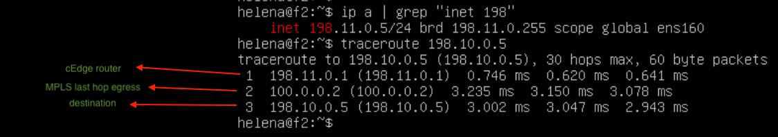
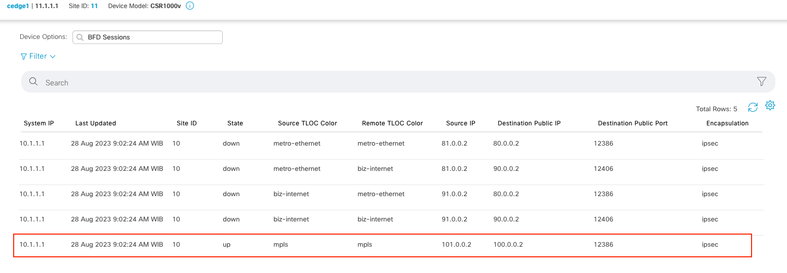
And for Customer 1, because these are SD-WAN edges, all we need to check is its BFD Connectivity on vManage
cEdge 0

cEdge 1
End-to-End Testing
And now for Customer 2, if we do an end-to-end tracing from CE0 to CE1 and vice versa, we should see the traffic being routed through MPLS network
CE0
1
2
3
4
5
6
7
8
9
10
ce0#trace 192.168.1.1 source 192.168.0.1
Type escape sequence to abort.
Tracing the route to 192.168.1.1
VRF info: (vrf in name/id, vrf out name/id)
  1 1.0.0.110.ap.yournet.ne.jp (110.0.0.1) 1 msec 1 msec 1 msec
  2 2.2.12.2 [MPLS: Labels 18/25 Exp 0] 3 msec 2 msec 3 msec
  3 2.2.23.3 [MPLS: Labels 18/25 Exp 0] 3 msec 3 msec 2 msec
  4 2.2.34.4 [MPLS: Labels 18/25 Exp 0] 3 msec 3 msec 3 msec
  5 111.0.0.1 [MPLS: Label 25 Exp 0] 3 msec 2 msec 2 msec
  6 111.0.0.2 3 msec 4 msec *
CE1
1
2
3
4
5
6
7
8
9
10
ce1#trace 192.168.0.1 source 192.168.1.1
Type escape sequence to abort.
Tracing the route to 192.168.0.1
VRF info: (vrf in name/id, vrf out name/id)
  1 111.0.0.1 1 msec 1 msec 1 msec
  2 2.2.45.4 [MPLS: Labels 19/25 Exp 0] 3 msec 3 msec 3 msec
  3 2.2.34.3 [MPLS: Labels 19/25 Exp 0] 3 msec 3 msec 3 msec
  4 2.2.23.2 [MPLS: Labels 19/25 Exp 0] 3 msec 3 msec 3 msec
  5 1.0.0.110.ap.yournet.ne.jp (110.0.0.1) [MPLS: Label 25 Exp 0] 3 msec 3 msec 2 msec
  6 2.0.0.110.ap.yournet.ne.jp (110.0.0.2) 3 msec *  4 msec
And if we do end-to-end trace on Customer 1, we can see it also being routed successfully through MPLS network
endpoint on cEdge 0
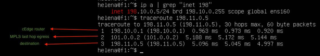
endpoint on cEdge 1