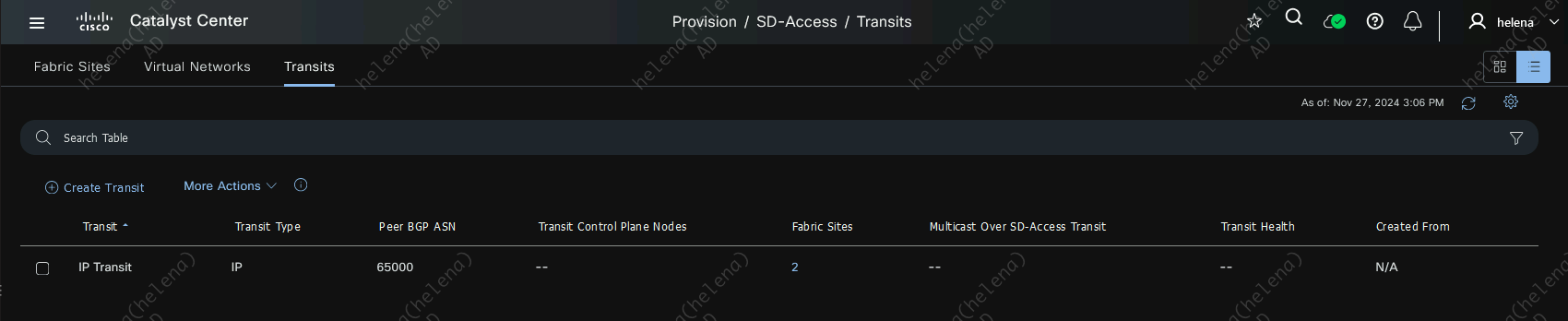
Cisco SD-Access IP Transit
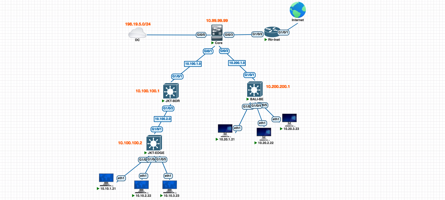
In Software-Defined Access (SDA), IP Transit enables communication between the SDA fabric and an external network. The border node establishes BGP peering with the core switch to exchange routing information. This allows proper advertisement of external routes into the fabric and fabric prefixes into the core network, allowing traffic flow between internal fabric devices and external networks.
Configuring Core Switch
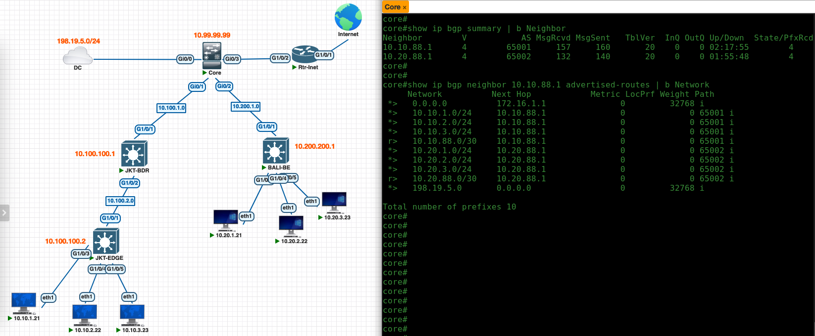
On the core switch, we configure 1 vlan for each site that has 1 VRF or Layer 3 Virtual Network, then we set up a BGP configuration using AS Number of 65000 to establish neighborship to each Border Node. Here also we advertise external networks that we want the internal fabric to be able to access
1
2
3
4
5
6
7
8
9
10
11
12
13
14
15
16
17
18
19
20
21
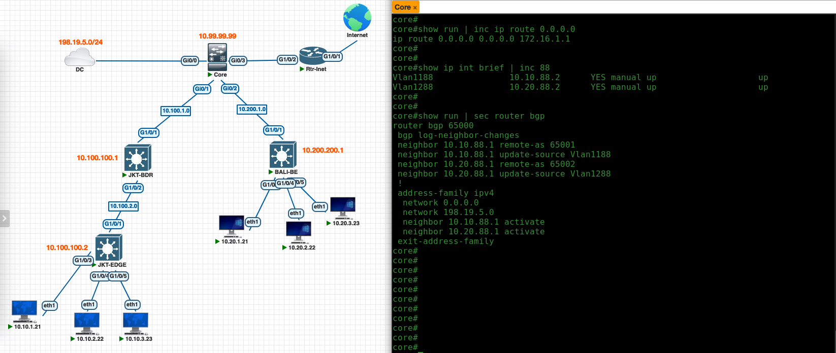
## Default route to Internet Router
ip route 0.0.0.0 0.0.0.0 172.16.1.1
## Peer-to-peer connection between core and border
interface vlan 1188
ip address 10.10.88.2 255.255.255.252
interface vlan 1288
ip address 10.20.88.2 255.255.255.252
## BGP
router bgp 65000
neighbor 10.10.88.1 remote-as 65001
neighbor 10.10.88.1 update-source Vlan1188
neighbor 10.20.88.1 remote-as 65002
neighbor 10.20.88.1 update-source Vlan1288
## Advertising internet and DC networks
address-faimily ipv4
network 0.0.0.0
network 198.19.5.9 255.255.255.0
Configuring IP Transit on DNAC
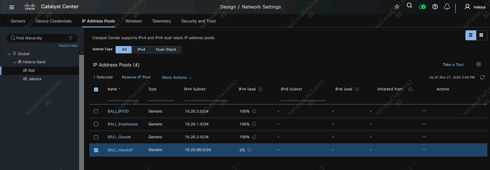
On DNAC, create an IP Pool for Border Handoff for each site. This pool will later be used as a /30 p2p network between Core and Border

Next on Provision » IP Transit, create an IP Transit with the Core’s BGP AS Number
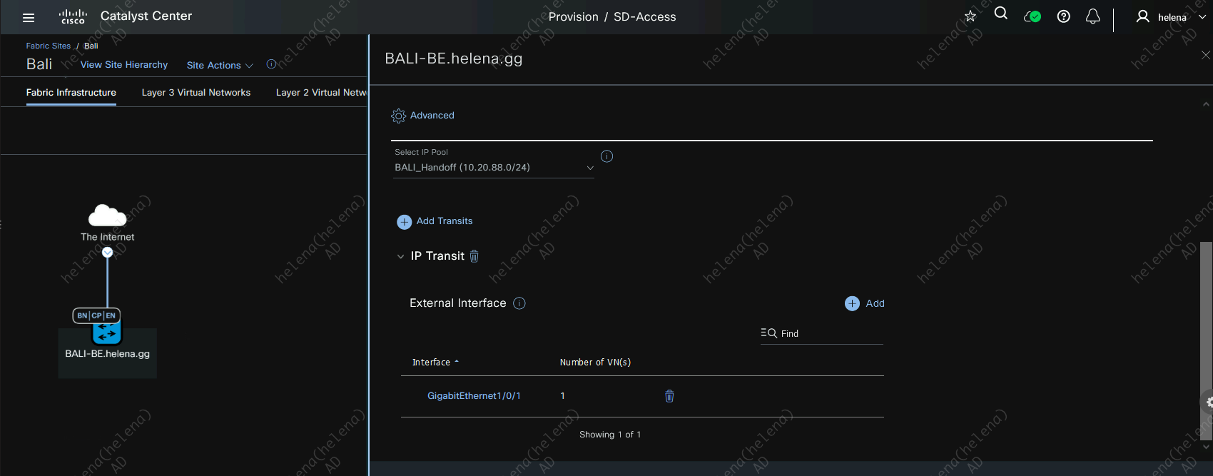
On Jakarta Site, assign this IP Transit to the border using the externally facing interface with the IP Pool created earlier
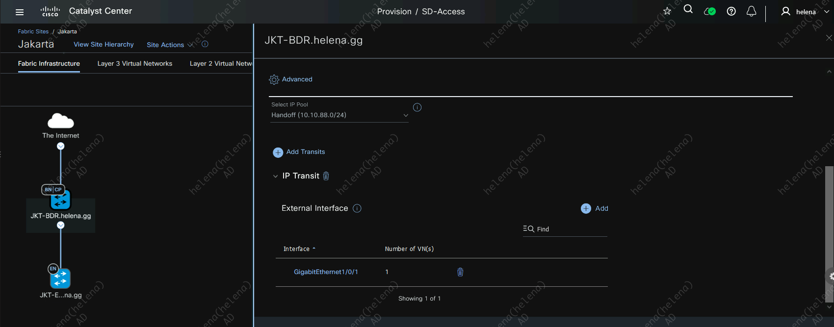
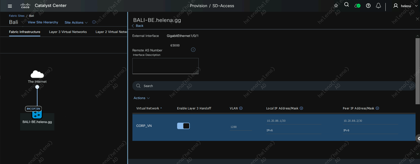
Here for every L3 Virtual Network we have, we will assign a VLAN for the p2p connection to the Core
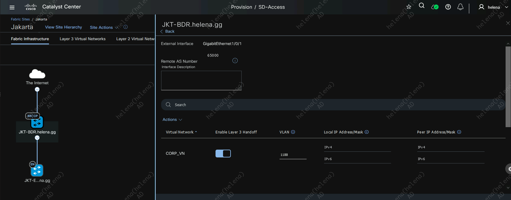
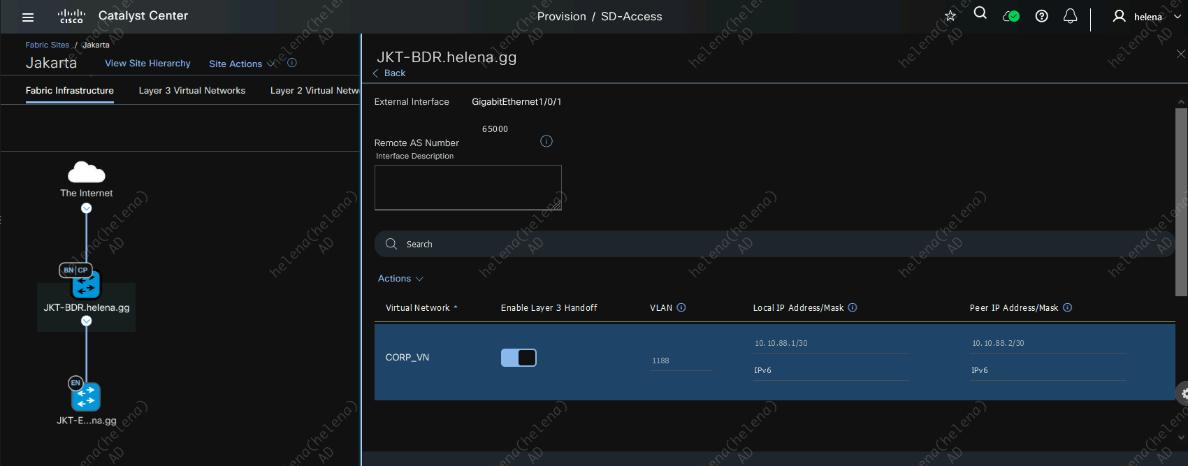
After this IP Transit is active, the IP Address will be automatically populated using a /30 network on the pool
Do the same for the Bali Site
Verifying IP Transit
Now on the Core Switch, we should see the BGP neighborship established to the Border Nodes, and segments of each sites along with the internet and DC segments are advertised in BGP
On the Border side, the BGP neighborsip has also been established using the IP Address from the pool with the VLAN we configured on DNAC, and we can verify that Border is getting the external networks thats being advertised through this BGP neighborship
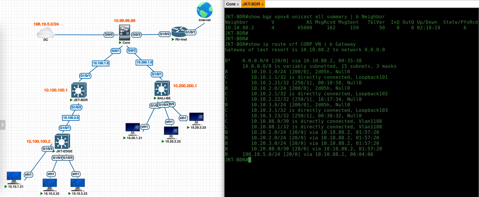
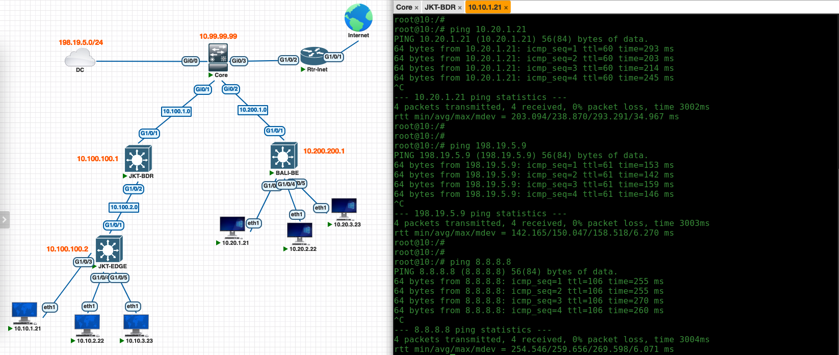
And on the clients side, now we can connect to clients on the other sites as well as to the datacenter and to internet