Cisco SD-WAN - Onboard Edge Routers
What is Edge Routers?
In Cisco SD-WAN, edge routers are devices deployed at branch locations that connect the local area network (LAN) of the branch to the wider SD-WAN network.
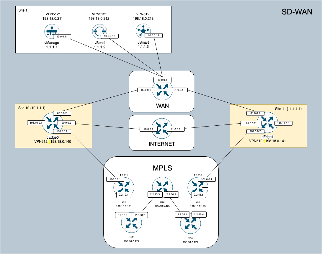
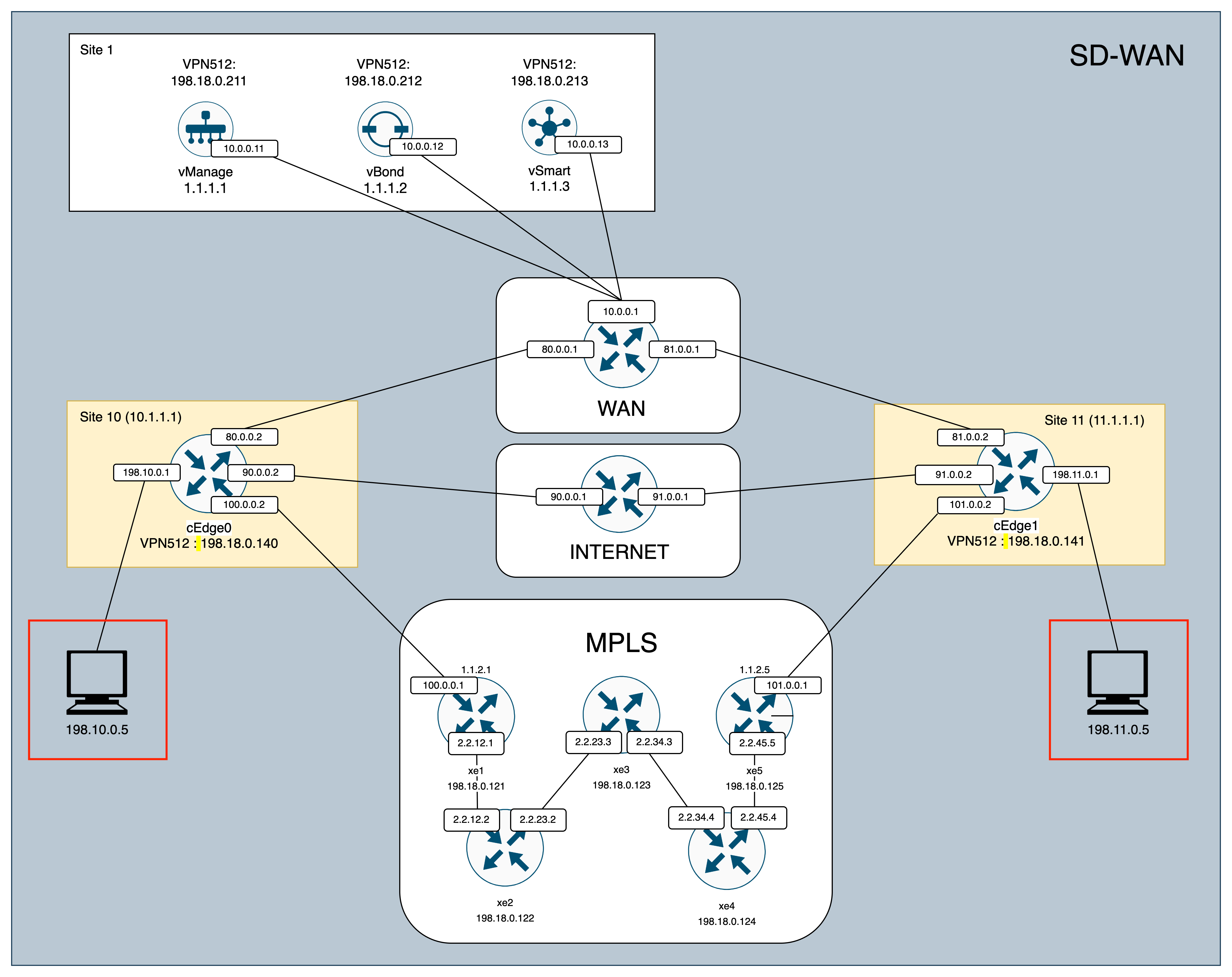
For this deployment, we will use Cisco Virtual Router CSR1000V with this topology
Creating Provisioning File on Cisco Smart Account
In the newer version of Cisco SD-WAN, we cannot just simply import the Edge Router List to vManage, we have generate the the Router List using a Provisioning File through Cisco Smart Account. Luckily, it is free to set up a smart account so anyone can do it.
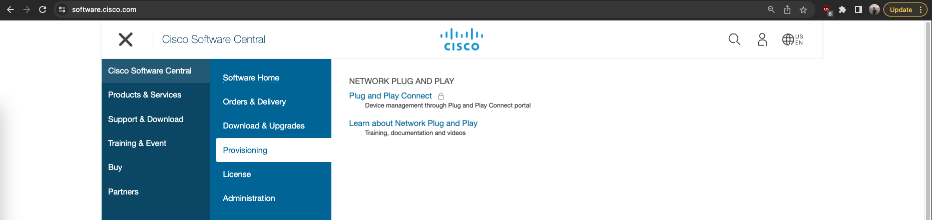
After signing up, go to https://software.cisco.com/ and choose Software Central » Provisioning » Plug and Play Connect
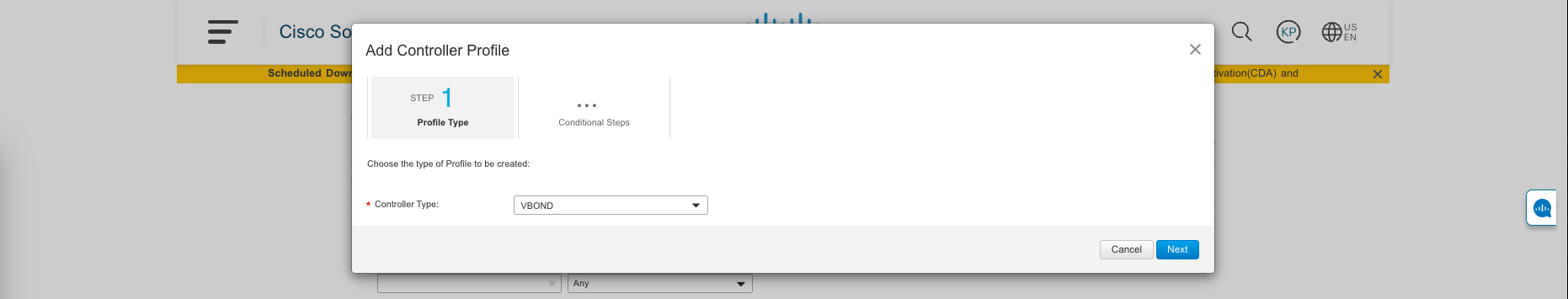
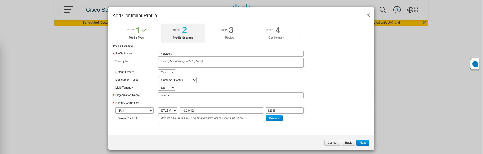
Then go to Controller Profiles » Add Profile, choose VBOND
After that, fill out the name of the profile and the IP Address of the vBond on the deployment
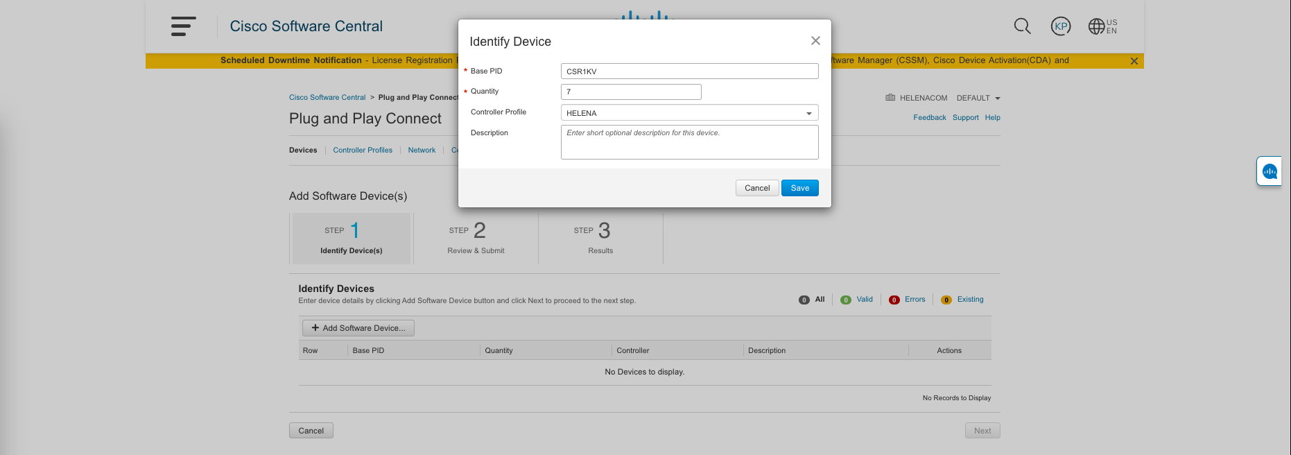
Next, go to Devices » Add Software Devices, select Add Software Device
Choose Base ID of CSR1K, which is our virtual router, then the quantity, we can type how many as we need, and lastly the controller profile of the one we just created
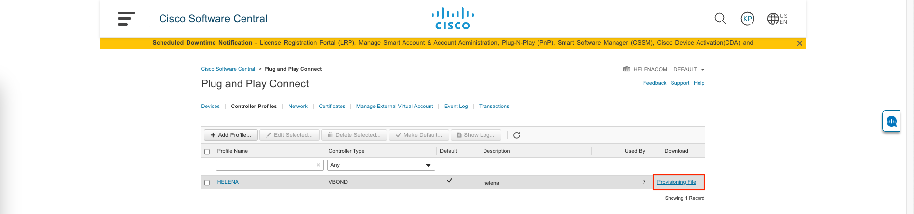
Lastly, now we can download the Provisioning File
Importing the Provisioning File
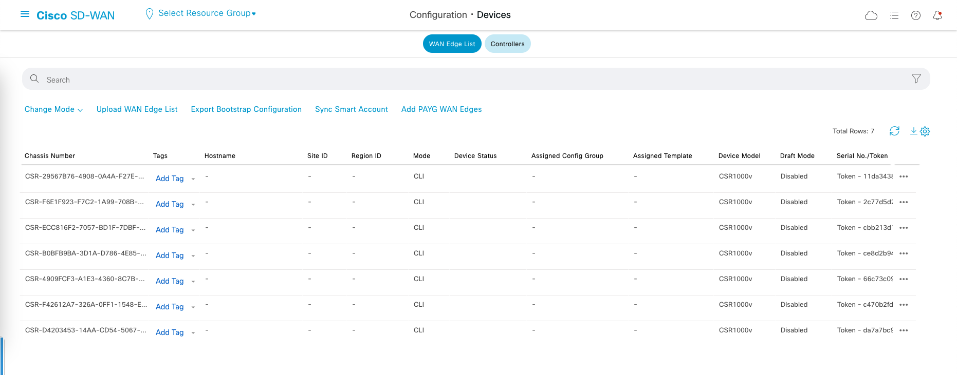
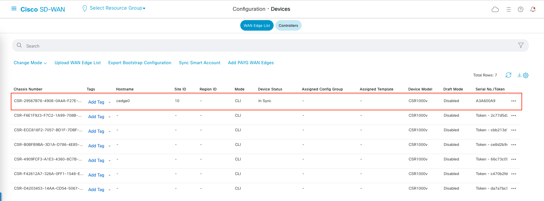
Go to vManage » Configuration » Devices, select Upload WAN Edge List
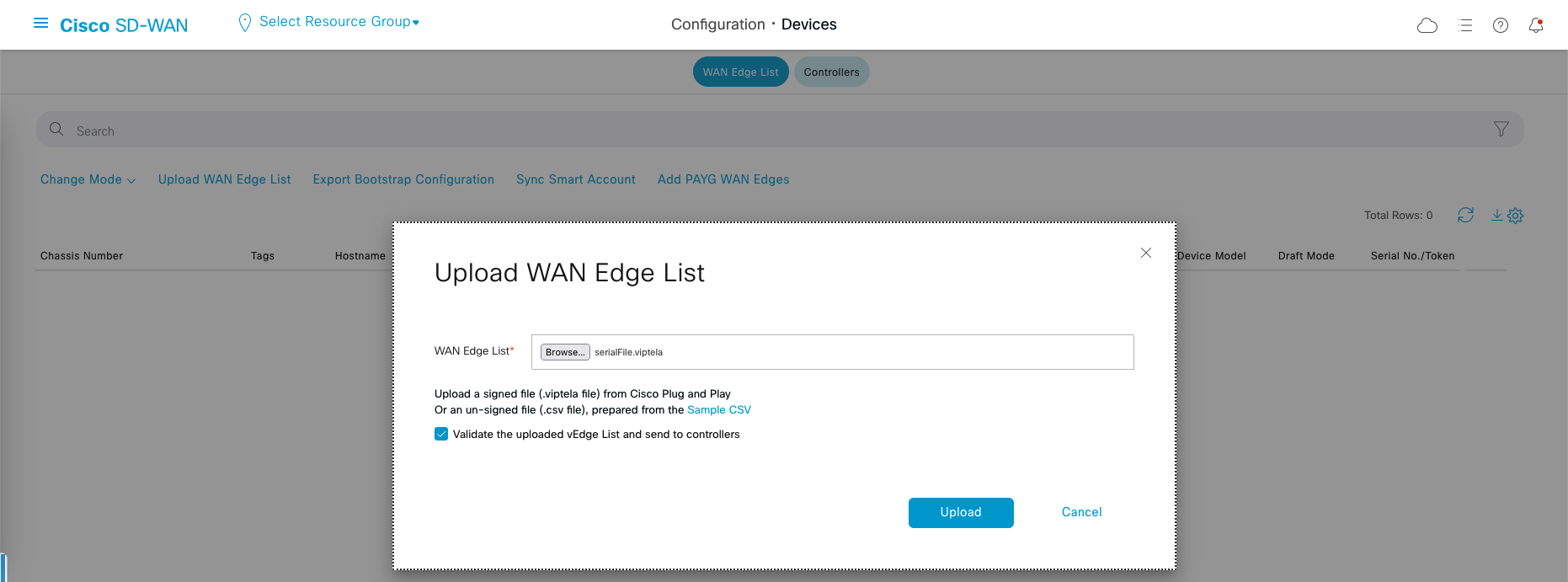
After uploading, we should see 7 devices listed on the WAN Edge List
Configure the Edge Router CSR1000V
Download the OVA from cisco and deploy it as a normal ova file

After it boots, just access it through console and configure it with this config
1
2
3
4
5
6
7
8
9
10
11
12
13
14
15
16
17
18
19
20
21
22
23
24
25
26
27
28
29
30
31
32
33
34
35
36
37
38
39
40
config-transaction
 system
  system-ip 10.1.1.1
  site-id 10
  admin-tech-on-failure
  organization-name helena
  vbond 10.0.0.12
  exit
 commit

 interface GigabitEthernet1
  ip add 80.0.0.2 255.255.255.0
  no shut
  exit

 interface GigabitEthernet2
  ip add 198.18.0.140 255.255.255.0
  no shut
  exit

 ip route 0.0.0.0 0.0.0.0 80.0.0.1

 interface Tunnel1
  no shut
  ip unnumbered GigabitEthernet1
  tunnel source GigabitEthernet1
  tunnel mode sdwan
  exit

 sdwan
  interface GigabitEthernet1
   tunnel-interface
   encapsulation ipsec
   color default
   allow-service all
   allow-service netconf
   exit
  exit
 exit
commit
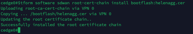
After that, we’ll install the ROOT CA Certificate, which will be copied from a TFTP Server on 80.0.0.1

Then run this command to install it
1
request platform software sdwan root-cert-chain install bootflash:helenagg.cer
Onboarding the Edge Router to vManage
Now go back to the WAN Edge List page on vManage, and Generate Bootstrap Configuration for the first device on the list
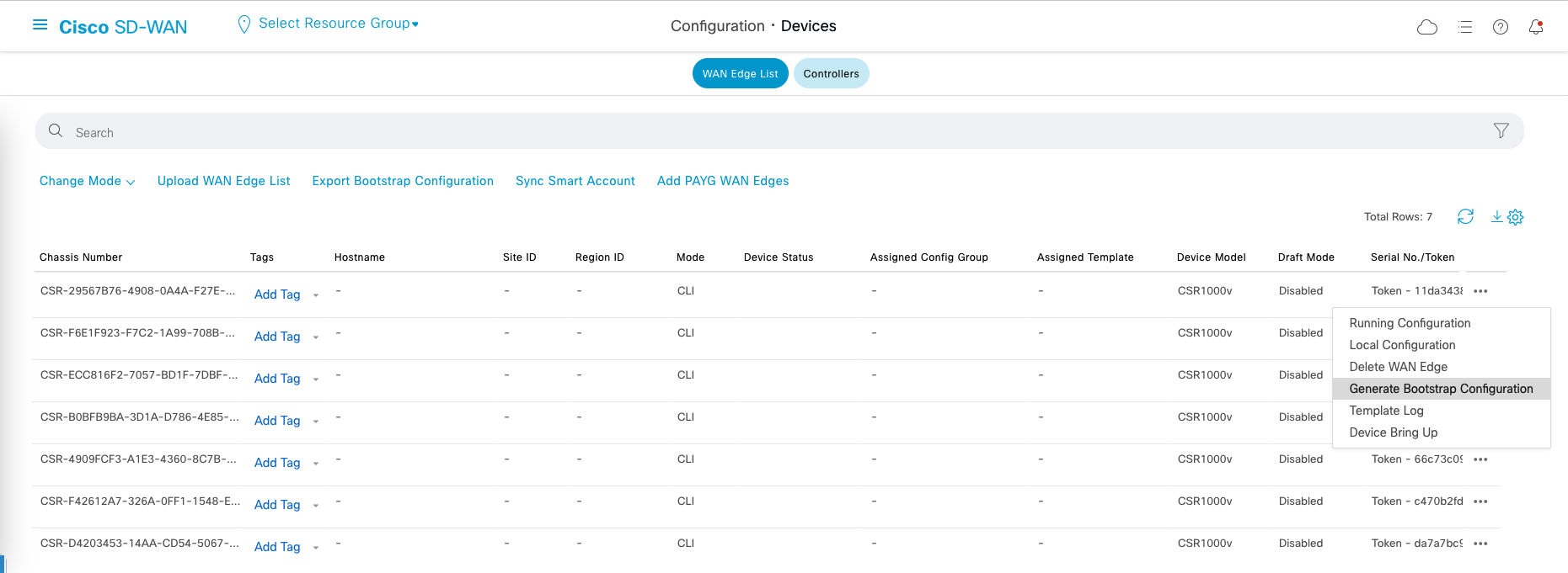
All we need is the UUID and OTP
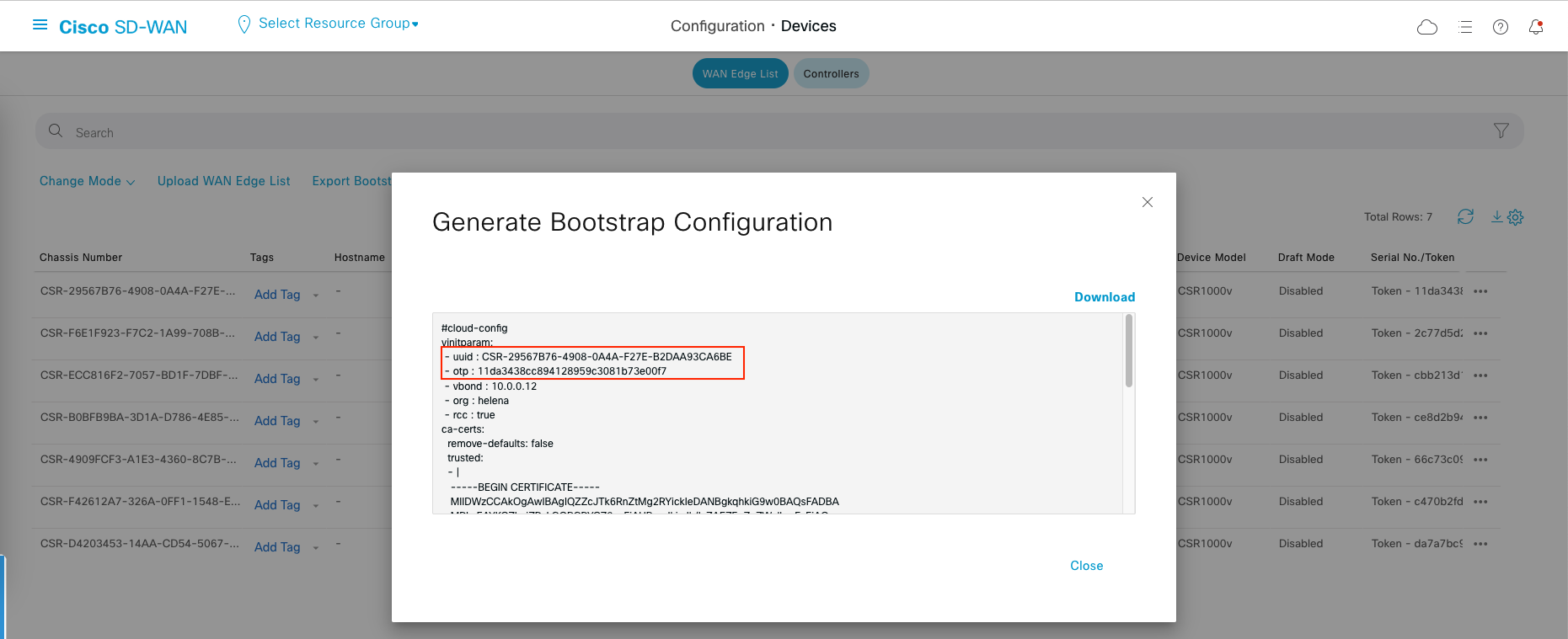
Go to the CSR1000V, and run this command
1
request platform software sdwan vedge_cloud activate chassis-number <UUID> token <OTP>
After that, we’ll start seeing log messages saying vmanage-admin doing its stuff to provision the router
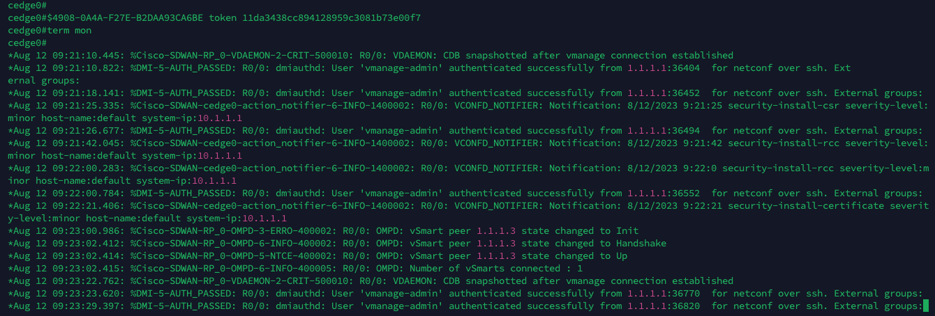
And after sometime, the process will finish and this router should be onboarded to vManage
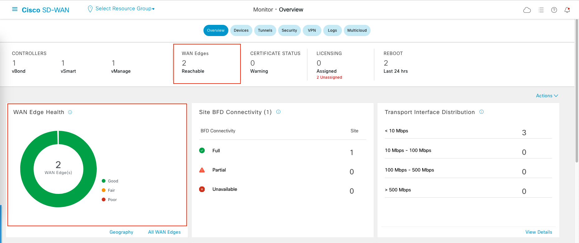
Repeat the process for the second router, and then we end up with this
Creating Templates
Templates are pre-defined configurations that allow us to quickly deploy and manage SD-WAN devices and policies within the network infrastructure.
- Device templates cover the overall configuration of an SD-WAN device, ensuring consistent setup across the network.
- Feature templates focus on specific functionalities within the network, allowing us to fine-tune policies for traffic management, security, and other specific aspects.
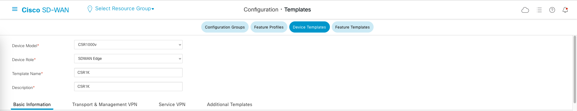
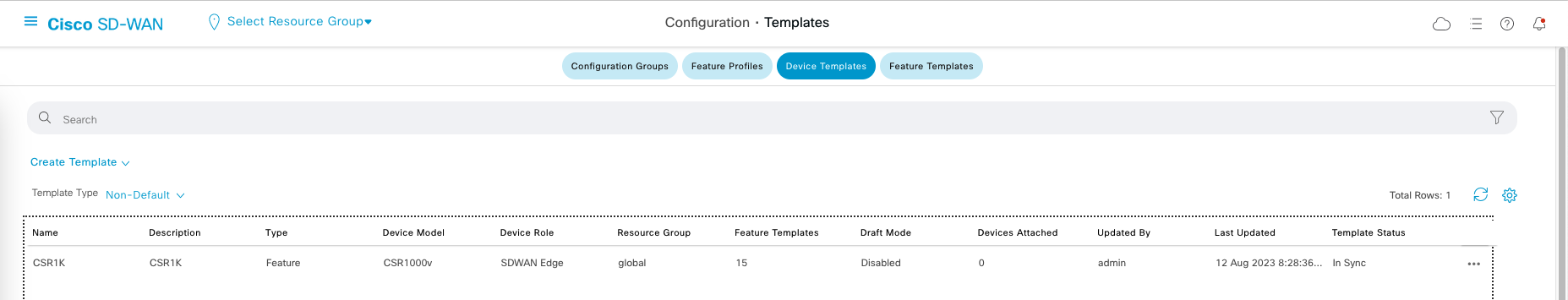
To configure templates, go to Configuration » Templates, lets create a new Device Template
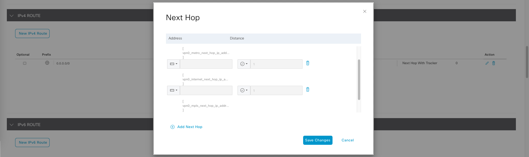
Add IPv4 Route to 0.0.0.0/0, then add next hop with parameterized values, so we can customized the value later on based on individual router.
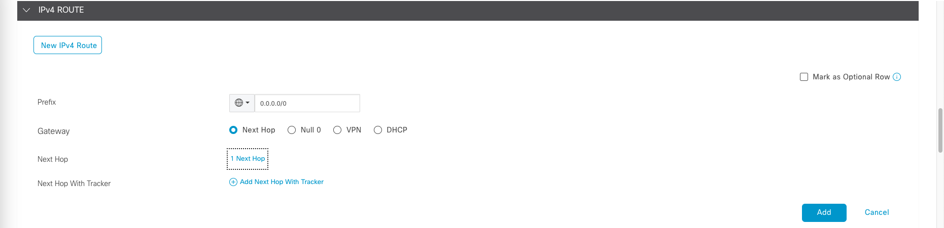
Here we will set up 3 next hop, 1 for each WAN link, then save it.
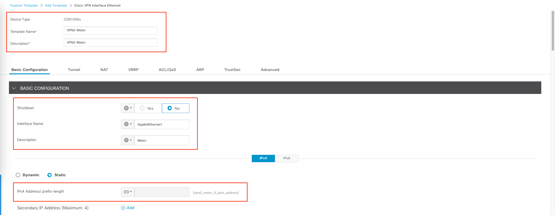
Next we create Feature template for the interface going to the Metro WAN
For the Interface name, we’ll hardcode it to all routers to use GigabitEthernet1 for the connection.
Then we enable tunneling
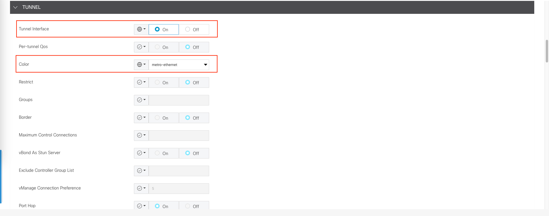
Next allow services as we see fit, then save it.
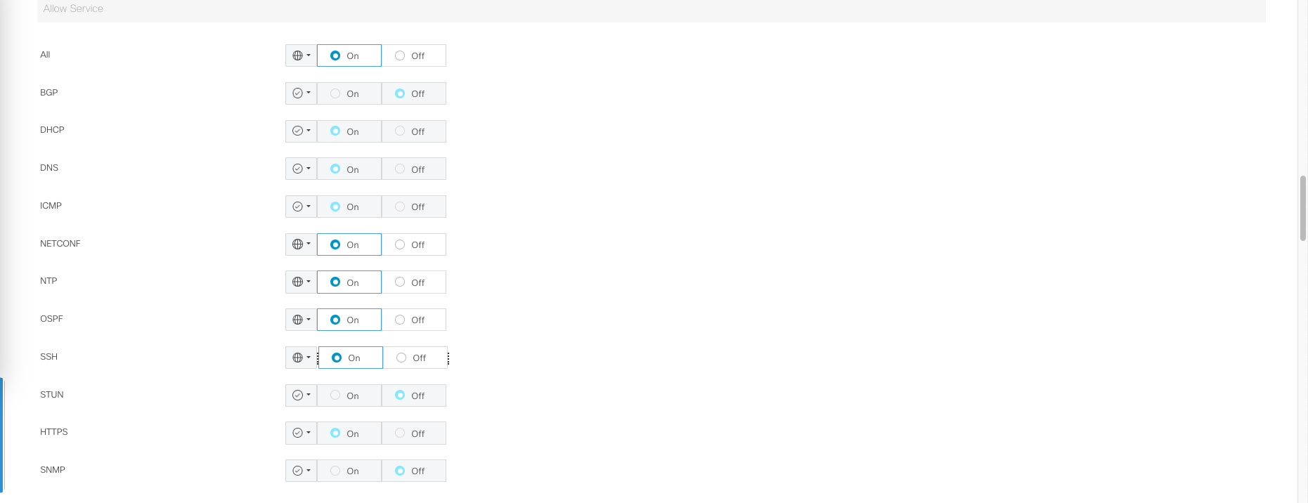
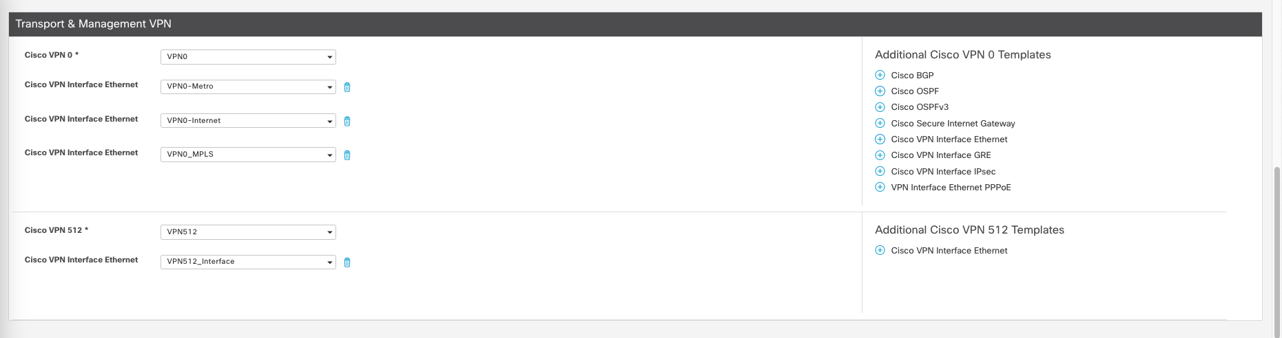
Then repeat it for the Internet and MPLS Interface so we have 3 Feature Templates for VPN0, the configuration should be pretty much the same except for MPLS where we enable restriction on tunneling section so the traffic is isolated and cannot cross to other WAN connection.

Then for VPN512, we can repeat the same process except for the Interface we don’t neet to use tunneling. Everything else should be roughly the same.
And this is what we end up with
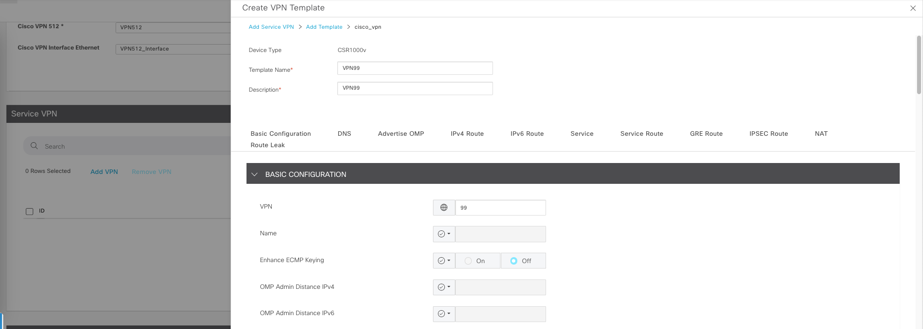
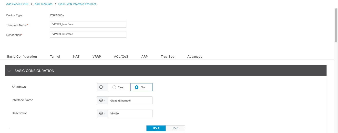
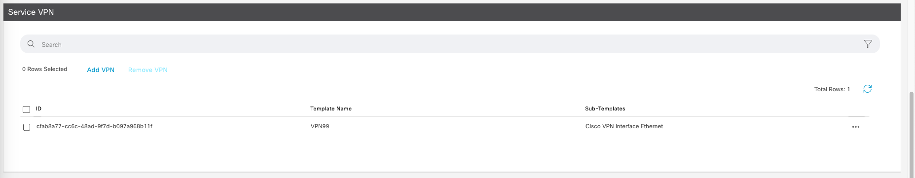
Next, we create service VPN, this is the VPN for the interface facing the local environment of the branch routers.
Then advertise the OMP for Static, Connected, and OSPF. We honestly dont need OSPF but lets just include it anyway
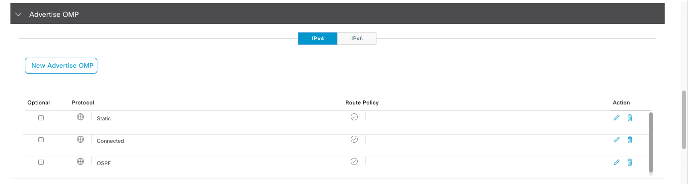
OMP stands for “Overlay Management Protocol.” It is a proprietary routing protocol developed by Cisco to manage and control the overlay network created by SD-WAN devices. OMP is a key component of Cisco’s SD-WAN solution and plays a crucial role in enabling dynamic and intelligent routing of traffic across the wide area network
Then create a Feature Template for this interface as well
And this is what we end up with for the service VPN
Now save the Device Template
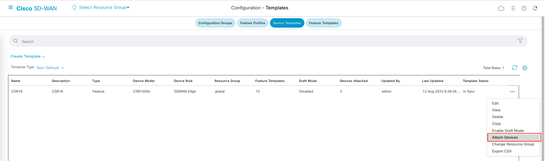
Attaching Device to a Template
Now select Attach Device on the template
Select the 2 CSR1K routers
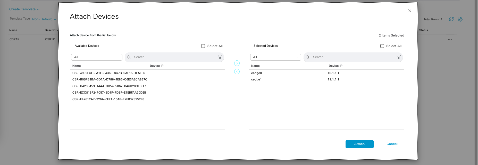
This will generate a page where we have some configuration parameters with empty values, this is the parameter that we have been setting up within the Feature Templates.
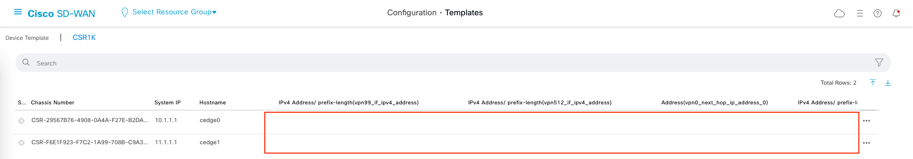
Select Edit Device Template
Fill out the values following the topology


This is after the edit is done, Next and choose Configure Devices.

Then the Template Configuration will be pushed to the devices
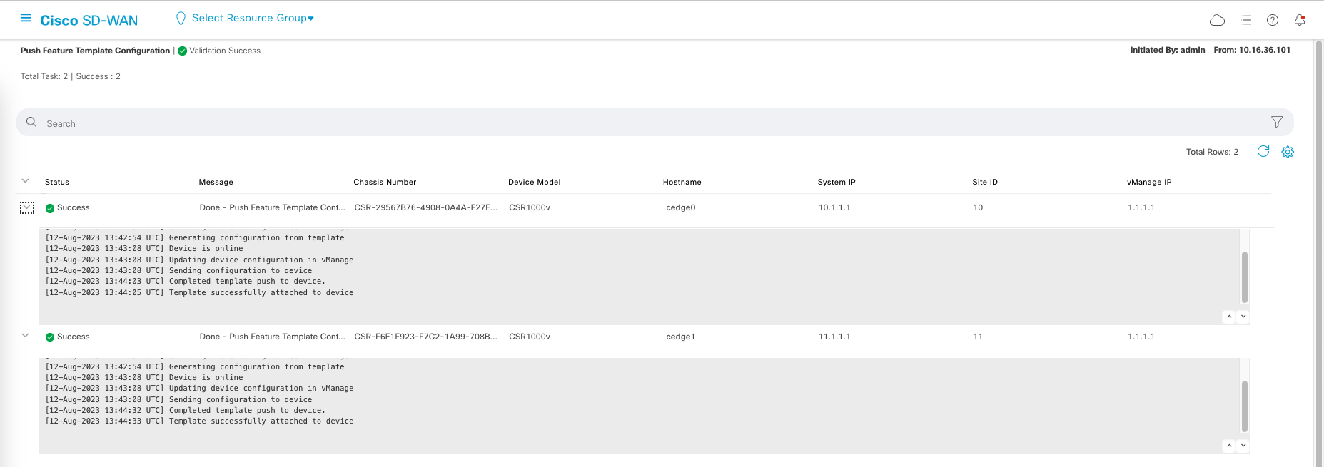
And that’s pretty much it.
Monitoring
After all the config is done, we can go to individual device » Real Time » BFD Session
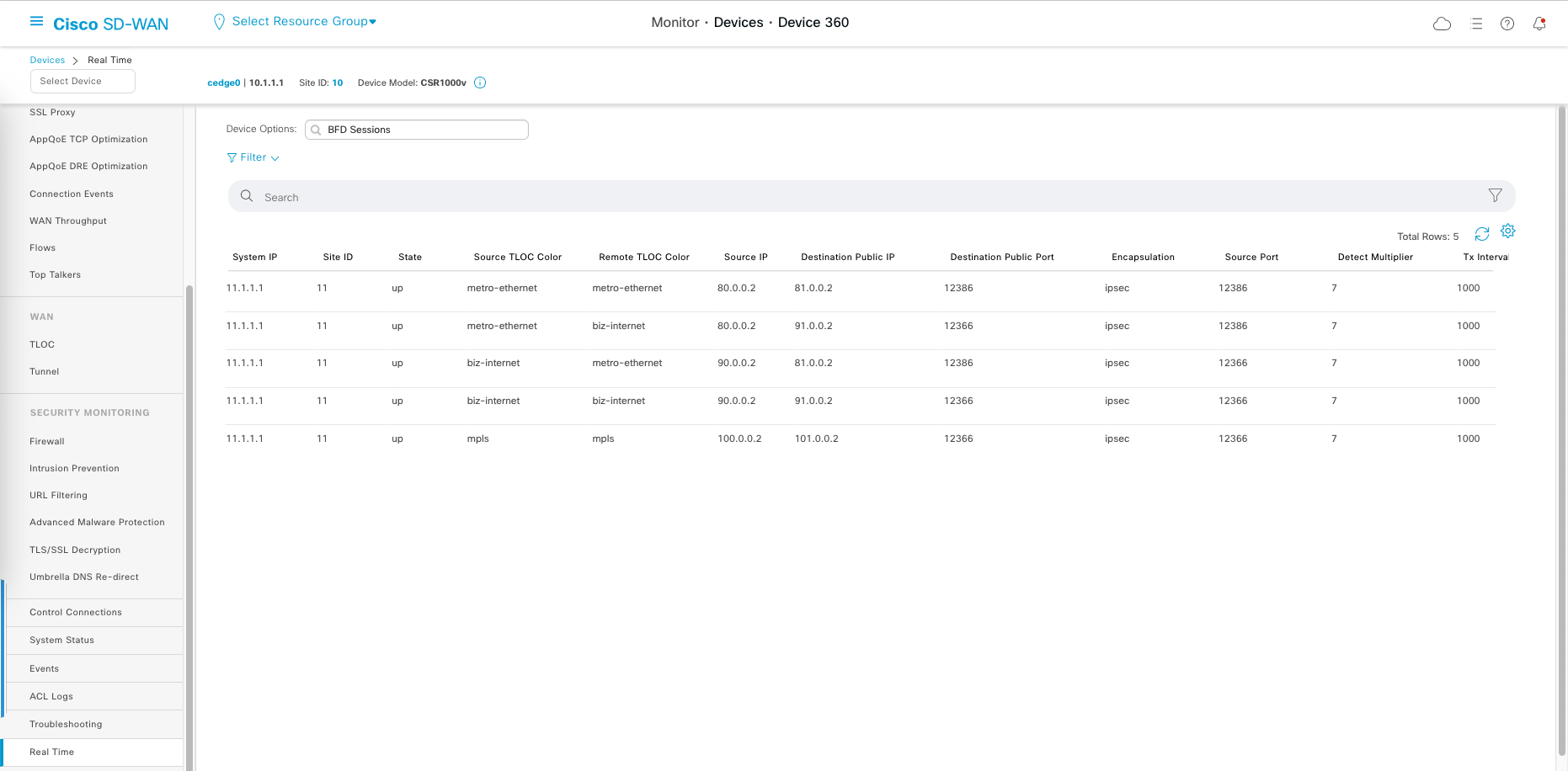
Here we can see the link path between WAN connection and the status of these connections. Here also we can see that MPLS connection is isolated because we enable the restriction on it’s tunnel.
BFD stands for “Bidirectional Forwarding Detection.” It is a protocol used to detect failures in communication paths between SD-WAN devices, such as routers or edge devices.
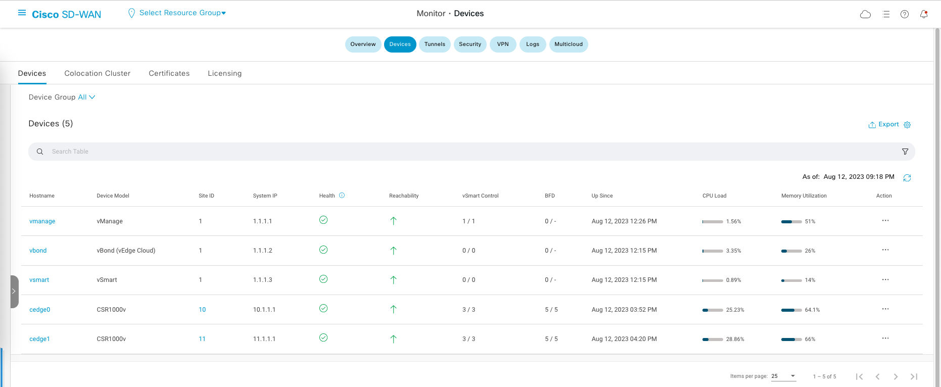
Under Monitor » Devices, we can also see the status of each device in the inventory
If we SSH to one of our edge routers, we can also validate some configurations
1
2
3
4
5
6
7
8
9
10
11
12
cedge0#show sdwan control connections

PEER    PEER PEER            SITE       DOMAIN PEER                                    PRIV  PEER                                    PUB                                           GROUP
TYPE    PROT SYSTEM IP       ID         ID     PRIVATE IP                              PORT  PUBLIC IP                               PORT  LOCAL COLOR     PROXY STATE UPTIME      ID
----------------------------------------------------------------------------------------------------------------------------------------------------------------------------------------
vsmart  dtls 1.1.1.3         1          1      10.0.0.13                               12446 10.0.0.13                               12446 metro-ethernet  No    up     0:10:25:10  0
vsmart  dtls 1.1.1.3         1          1      10.0.0.13                               12446 10.0.0.13                               12446 biz-internet    No    up     0:10:24:56  0
vsmart  dtls 1.1.1.3         1          1      10.0.0.13                               12446 10.0.0.13                               12446 mpls            No    up     0:10:24:59  0
vbond   dtls 0.0.0.0         0          0      10.0.0.12                               12346 10.0.0.12                               12346 metro-ethernet  -     up     0:10:25:11  0
vbond   dtls 0.0.0.0         0          0      10.0.0.12                               12346 10.0.0.12                               12346 biz-internet    -     up     0:10:24:56  0
vbond   dtls 0.0.0.0         0          0      10.0.0.12                               12346 10.0.0.12                               12346 mpls            -     up     0:10:24:59  0
vmanage dtls 1.1.1.1         1          0      10.0.0.11                               13046 10.0.0.11                               13046 metro-ethernet  No    up     0:10:25:11  0
1
2
3
4
5
6
7
8
cedge0#show sdwan control local-properties

INTERFACE                IPv4            PORT   IPv4            IPv6                                    PORT    VS/VM COLOR            STATE CNTRL CONTROL/     LR/LB  CONNECTION   REMAINING   TYPE CON
                                                                                                                                                   STUN                                              PRF
-----------------------------------------------------------------------------------------------------------------------------------------------------------------------------------------------------------
GigabitEthernet1         80.0.0.2        12386  80.0.0.2        ::                                      12386    1/1  metro-ethernet   up     2      no/yes/no   No/No  0:00:00:05   0:01:33:25  N    5
GigabitEthernet3         90.0.0.2        12366  90.0.0.2        ::                                      12366    1/0  biz-internet     up     2      no/yes/no   No/No  0:00:00:06   0:01:33:39  N    5
GigabitEthernet4         100.0.0.2       12366  100.0.0.2       ::                                      12366    1/0  mpls             up     2     yes/yes/no   No/No  0:00:00:12   0:01:33:36  N    5
1
2
3
4
5
6
cedge0#show ip route vrf 99

      198.10.0.0/24 is variably subnetted, 2 subnets, 2 masks
C        198.10.0.0/24 is directly connected, GigabitEthernet5
L        198.10.0.1/32 is directly connected, GigabitEthernet5
m     198.11.0.0/24 [251/0] via 11.1.1.1, 10:27:57
End to End Testing
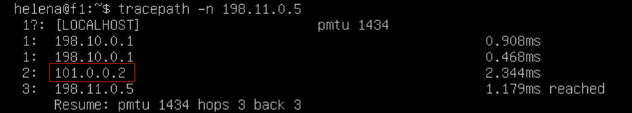
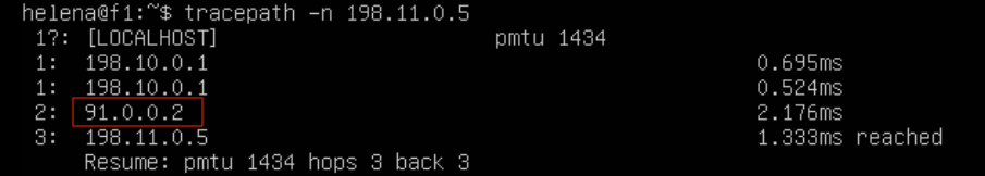
We have 1 endpoint device on each site, and now we will do the end to end connectivity testing.
Doing tracepath from server on site 10 to 11 gives an alternating path between the 3 WAN links

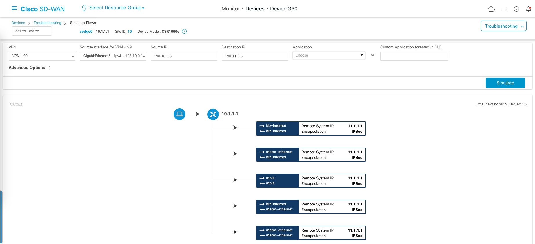
If we do a flow simulation, which we can access on Devices » Troubleshooting » Simulate Flows, we can see all the WAN paths available to be taken