VXLAN
VXLAN, or Virtual Extensible LAN, is a network virtualization technology that enables the creation of virtualized Layer 2 networks over an existing Layer 3 infrastructure. VXLAN overlays a Layer 2 network on top of a Layer 3 infrastructure, allowing for more flexible and scalable network design.
VXLAN Configuration
In this configuration we have 1 Spine and 2 Leaves, first we’ll configure the OSPF so all the siwtches can communicate properly to each other
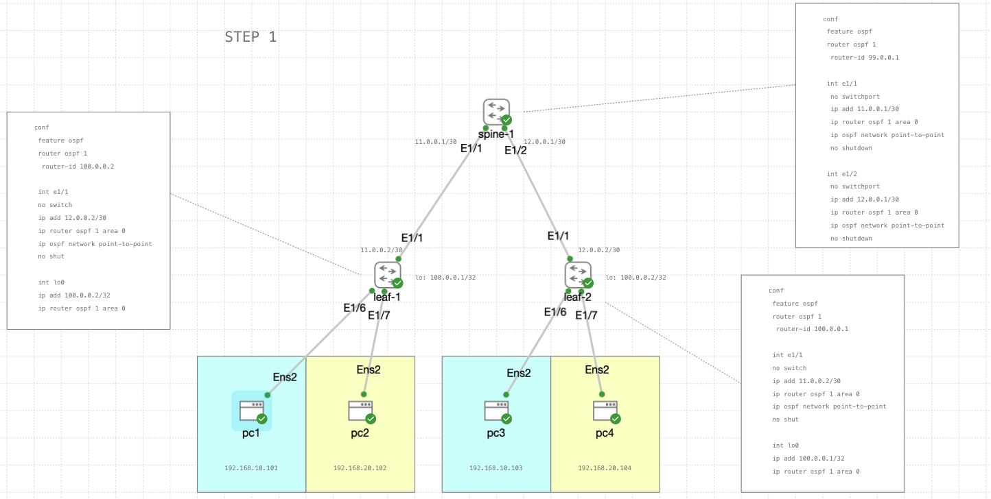
spine-1
1
2
3
4
5
6
7
8
9
10
11
12
13
14
15
16
17
18
conf
 feature ospf
 router ospf 1
  router-id 99.0.0.1

 int e1/1
 no switchport
 ip add 11.0.0.1/30
 ip router ospf 1 area 0
 ip ospf network point-to-point
 no shutdown

 int e1/2
 no switchport
 ip add 12.0.0.1/30
 ip router ospf 1 area 0
 ip ospf network point-to-point
 no shutdown
leaf-1
1
2
3
4
5
6
7
8
9
10
11
12
13
14
15
 conf
 feature ospf
 router ospf 1
 router-id 100.0.0.2

 int e1/1
  no switch
  ip add 12.0.0.2/30
  ip router ospf 1 area 0
  ip ospf network point-to-point
  no shut

 int lo0
  ip add 100.0.0.2/32
  ip router ospf 1 area 0
leaf-2
1
2
3
4
5
6
7
8
9
10
11
12
13
14
15
 conf
 feature ospf
 router ospf 1
 router-id 100.0.0.1

 int e1/1
  no switch
  ip add 11.0.0.2/30
  ip router ospf 1 area 0
  ip ospf network point-to-point
  no shut

 int lo0
  ip add 100.0.0.1/32
  ip router ospf 1 area 0
STEP 2
Next we configure the network virtualization overlay using the loopback interface
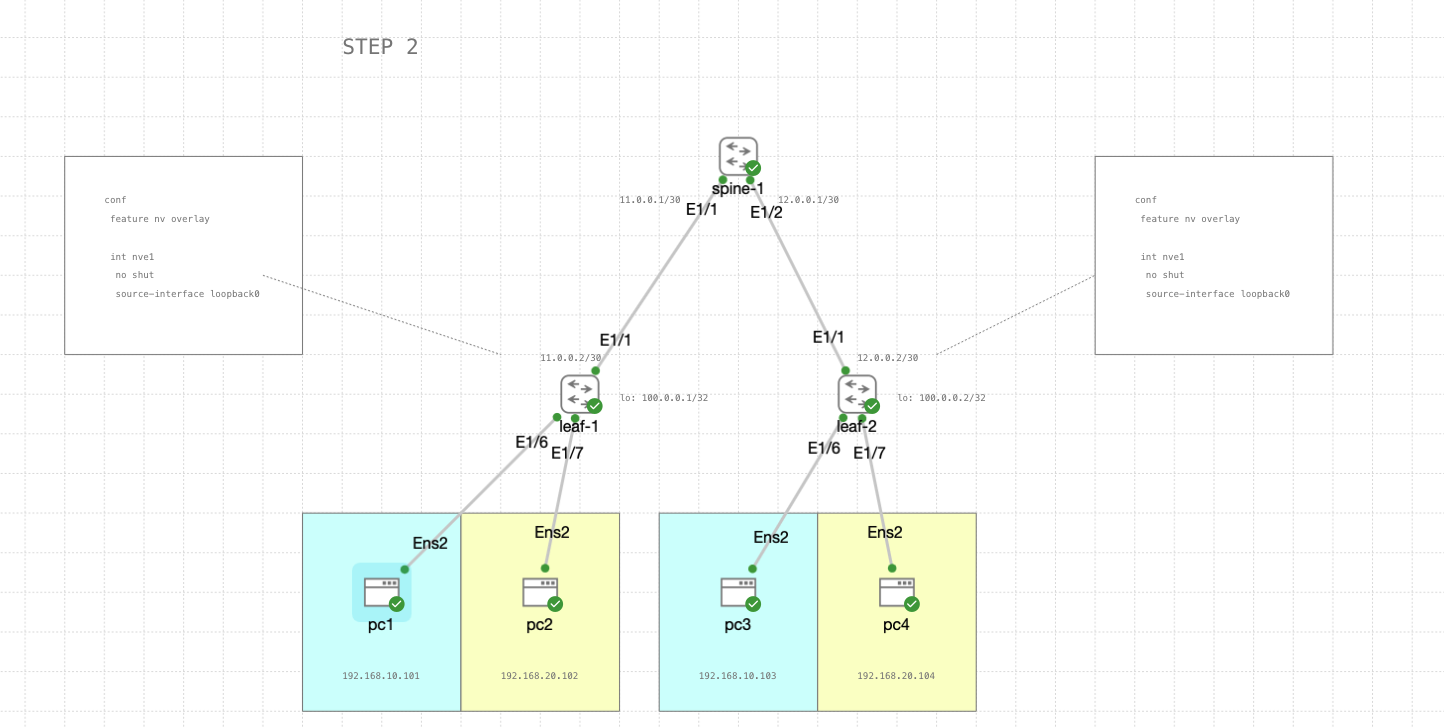
leaf-1 & leaf-2
1
2
3
4
5
6
conf
 feature nv overlay

 int nve1
  no shut
  source-interface loopback0
STEP 3
Next we enable VLAN-based segmentation for virtual networks, here each VLAN represents a separate segment of the network, and the vn-segment command assigns a unique identifier to each segment.

leaf-1 & leaf-2
1
2
3
4
5
6
7
8
conf
 feature vn-segment-vlan-based

 vlan 10
  vn-segment 1000

 vlan 20
  vn-segment 2000
STEP 4
Next configuration is to set up the NVE (Network Virtualization Edge) interface nve1 with membership to two VNIs (Virtual Network Identifiers), namely VNI 1000 and VNI 2000.
In this configuration NVEs are used to encapsulate traffic from multiple VNIs and replicate it to peer devices for further distribution across the network. Each VNI represents a separate virtual network, and the NVE forwards traffic between the physical network and the virtual networks.
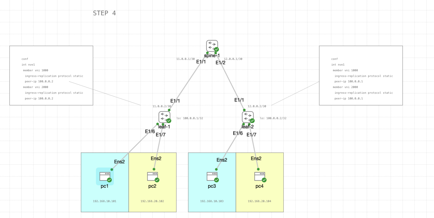
leaf-1
1
2
3
4
5
6
7
8
conf
 int nve1
  member vni 1000
   ingress-replication protocol static
   peer-ip 100.0.0.2
  member vni 2000
   ingress-replication protocol static
   peer-ip 100.0.0.2
leaf-2
1
2
3
4
5
6
7
8
conf
 int nve1
  member vni 1000
   ingress-replication protocol static
   peer-ip 100.0.0.1
  member vni 2000
   ingress-replication protocol static
   peer-ip 100.0.0.1
STEP 5
Lastly we set Ethernet1/6 and Ethernet1/7 as an access port to carry traffic for their respective VLAN
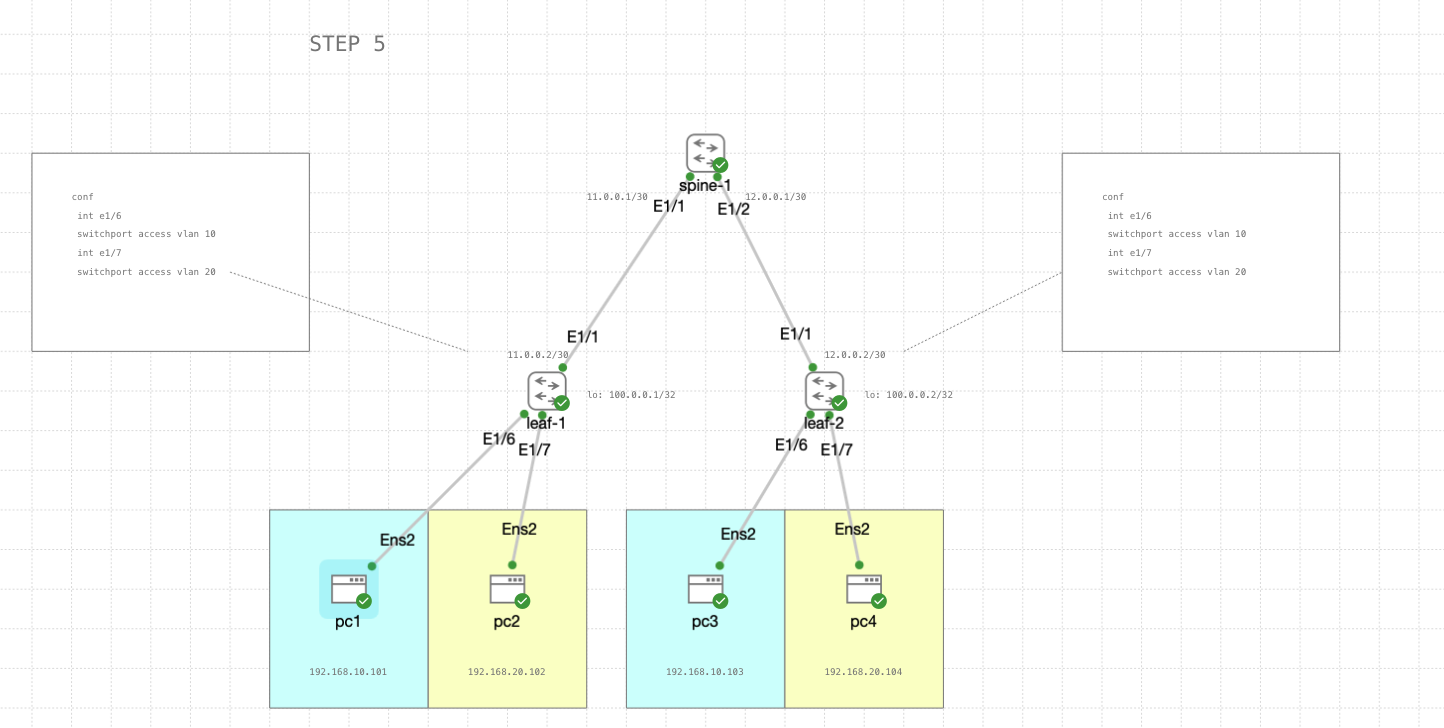
leaf-1 & leaf-2
1
2
3
4
5
6
conf
 int e1/6
  switchport access vlan 10

 int e1/7
  switchport access vlan 20
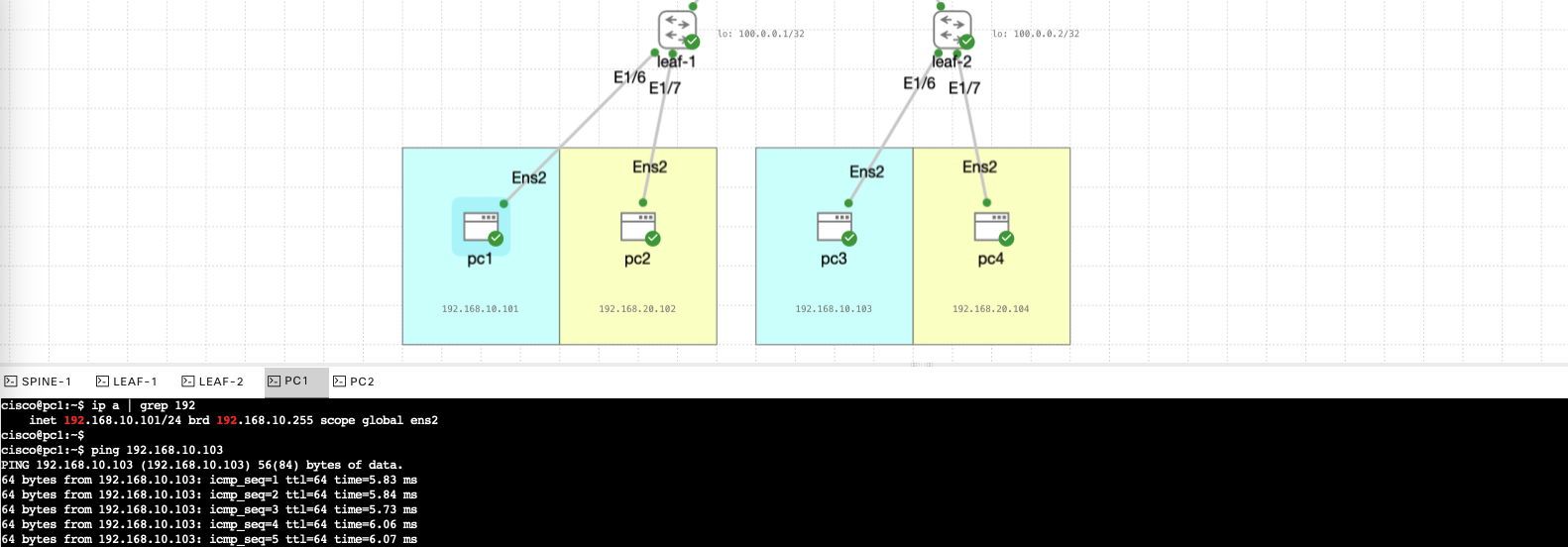
Testing VXLAN
Now we test the connectivity between each leaf, wether in the same vlan or different vlan.
Here’ pc1 pinging pc3 successfully
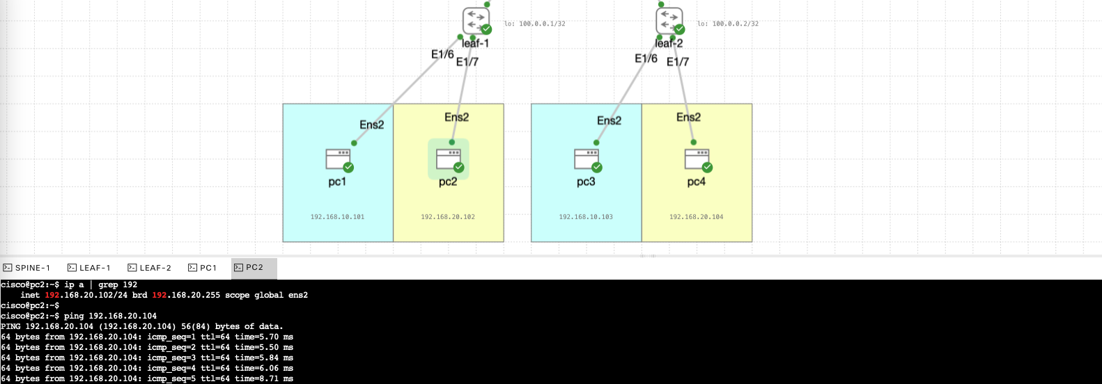
And here’s pc1 pinging pc4 on different vlan also successfully
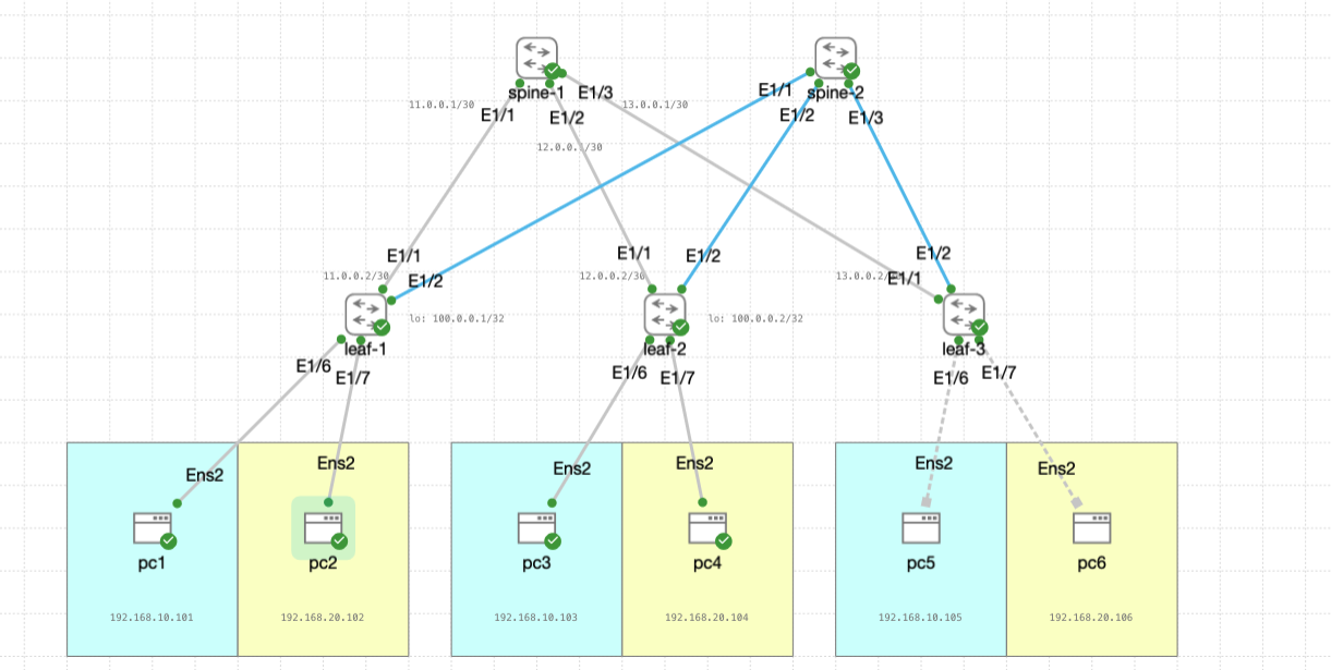
Scaling Up VXLAN
Next, we’ll scale up this topology by adding one more spine and leaf, so the configuration ends up like this
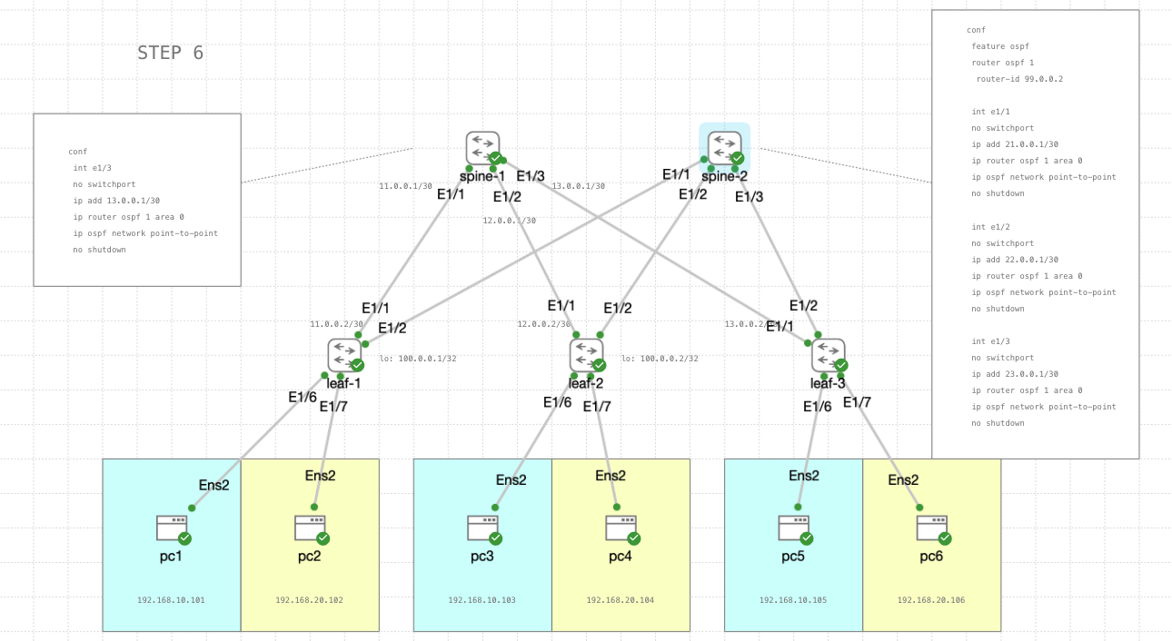
STEP 6
First lets configure OSPF to include the newly added switches on both spines
spine-1
1
2
3
4
5
6
7
conf
 int e1/3
 no switchport
 ip add 13.0.0.1/30
 ip router ospf 1 area 0
 ip ospf network point-to-point
 no shutdown
spine-2
1
2
3
4
5
6
7
8
9
10
11
12
13
14
15
16
17
18
19
20
21
22
23
24
25
26
conf
 feature ospf
 router ospf 1
  router-id 99.0.0.2

 int e1/1
 no switchport
 ip add 21.0.0.1/30
 ip router ospf 1 area 0
 ip ospf network point-to-point
 no shutdown

 int e1/2
 no switchport
 ip add 22.0.0.1/30
 ip router ospf 1 area 0
 ip ospf network point-to-point
 no shutdown

 int e1/3
 no switchport
 ip add 23.0.0.1/30
 ip router ospf 1 area 0
 ip ospf network point-to-point
 no shutdown
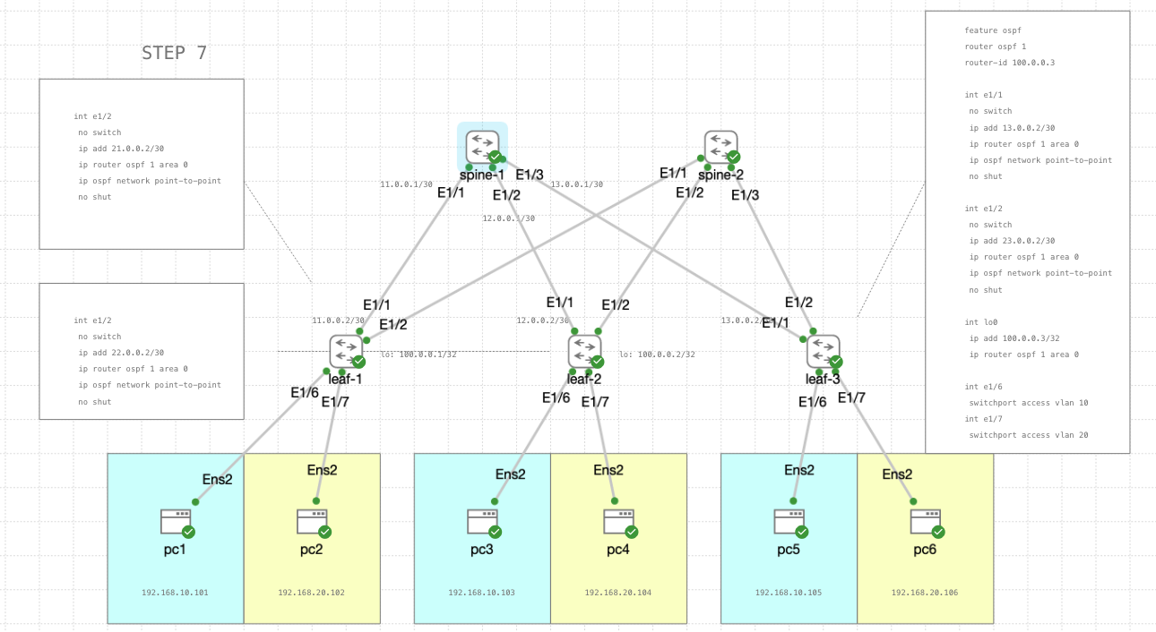
STEP 7
Continue the ospf configuration on leaf switches
leaf-1
1
2
3
4
5
6
7
conf
 int e1/1
  no switch
  ip add 21.0.0.2/30
  ip router ospf 1 area 0
  ip ospf network point-to-point
  no shut
leaf-2
1
2
3
4
5
6
7
conf
 int e1/1
  no switch
  ip add 22.0.0.2/30
  ip router ospf 1 area 0
  ip ospf network point-to-point
  no shut
leaf-3
1
2
3
4
5
6
7
8
9
10
11
12
13
14
15
16
17
18
19
20
21
22
23
24
25
26
27
28
conf
 feature ospf
 router ospf 1
 router-id 100.0.0.3

 int e1/1
  no switch
  ip add 13.0.0.2/30
  ip router ospf 1 area 0
  ip ospf network point-to-point
  no shut

 int e1/2
  no switch
  ip add 23.0.0.2/30
  ip router ospf 1 area 0
  ip ospf network point-to-point
  no shut

 int lo0
  ip add 100.0.0.3/32
  ip router ospf 1 area 0

 int e1/6
  switchport access vlan 10

 int e1/7
  switchport access vlan 20
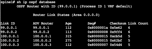
Taking a look at spine-1, we can see on its ospf database that all switches are now included in the ospf
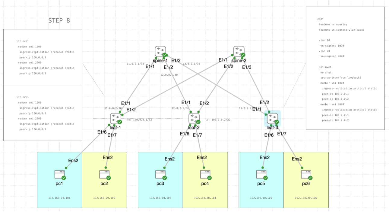
STEP 8
Lastly, now we configure the NVE interface to add leaf-3 as a peer
leaf-1 & leaf-2
1
2
3
4
5
6
7
8
conf
 int nve1
  member vni 1000
   ingress-replication protocol static
   peer-ip 100.0.0.3
  member vni 2000
   ingress-replication protocol static
   peer-ip 100.0.0.3
leaf-3
1
2
3
4
5
6
7
8
9
10
11
12
13
14
15
16
17
18
19
20
conf
 feature nv overlay
 feature vn-segment-vlan-based

 vlan 10
  vn-segment 1000
 vlan 20
  vn-segment 2000

 int nve1
  no shut
  source-interface loopback0
  member vni 1000
   ingress-replication protocol static
   peer-ip 100.0.0.1
   peer-ip 100.0.0.2
  member vni 2000
   ingress-replication protocol static
   peer-ip 100.0.0.1
   peer-ip 100.0.0.2
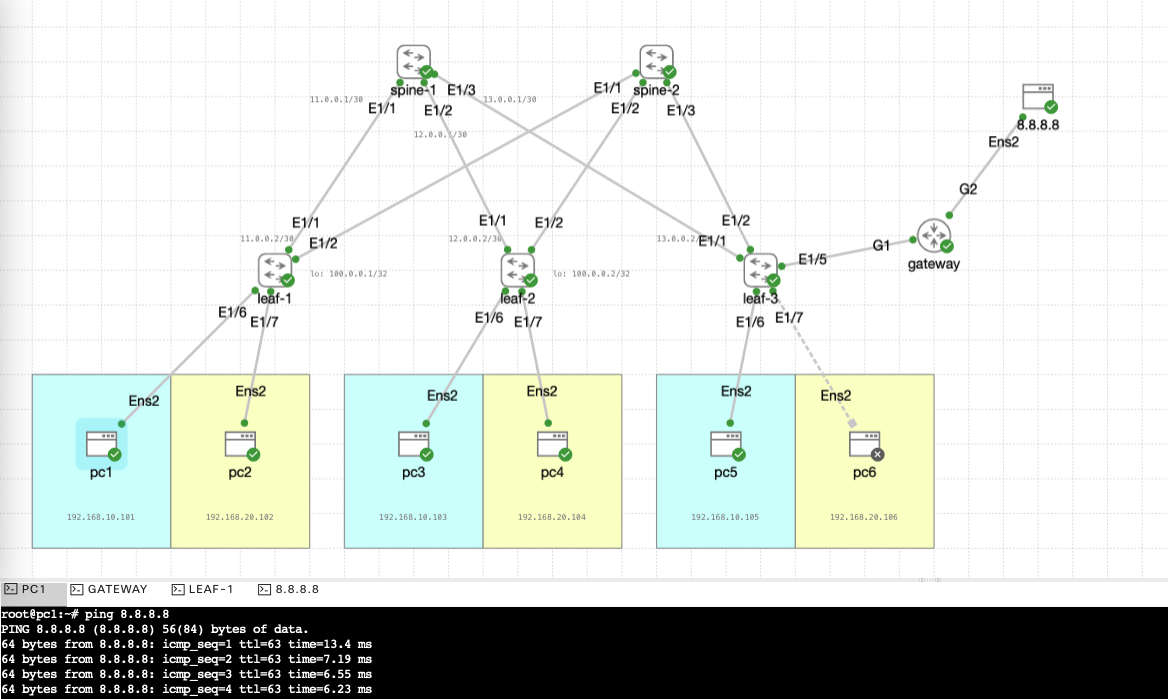
Testing Scaled-up VXLAN
Now we try pinging from pc1 to pc3 and pc5
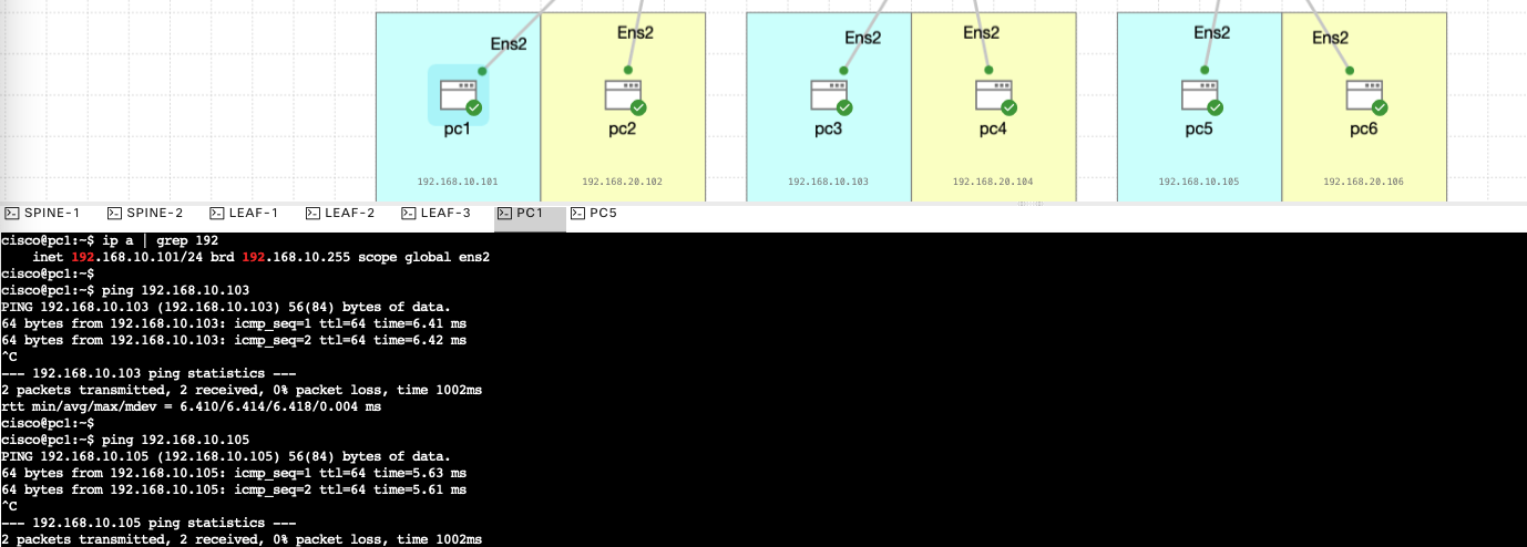
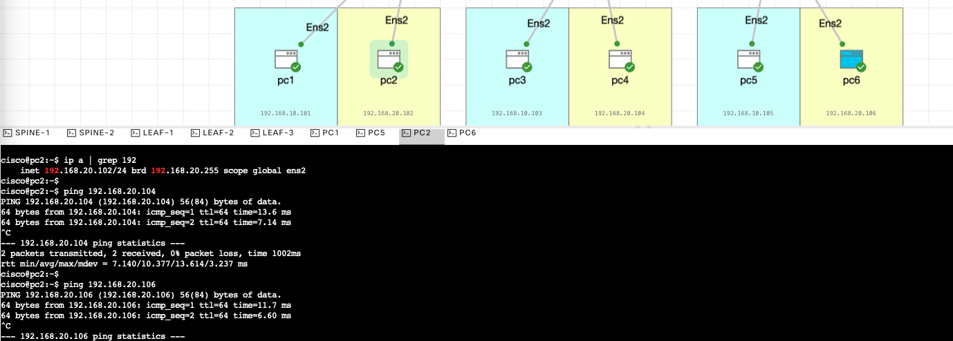
Same goes with pc2 to pc4 and pc6
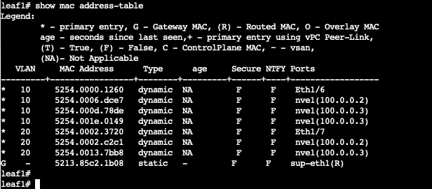
on a leaf switch, if we take a look at the mac address table, we can see that the leaf-1 learns mac address from 2 different ways, one is from its own interface and the other is from the nve interface
And lastly, if we want to have a layer3 out, we can add a gateway on any leaf for internet connection